Supercharge Your Innovation With Domain-Expert AI Agents!

Ultra-thin surface light source device

A light source device and surface light source technology, applied in the directions of light guides, optics, optical components, etc., can solve the problems of inability to use display devices and the thickness of light guide plates, and achieve the effect of being conducive to thinning and improving utilization.

Inactive Publication Date: 2015-04-08
SHENZHEN CHINA STAR OPTOELECTRONICS TECH CO LTD
View PDF6 Cites 0 Cited by
  • Summary
  • Abstract
  • Description
  • Claims
  • Application Information

AI Technical Summary

Problems solved by technology

However, this method makes the light guide plate thicker and cannot be used in ultra-thin display devices.

Method used


Image

  • Ultra-thin surface light source device
  • Ultra-thin surface light source device
  • Ultra-thin surface light source device

Examples


Embodiment 1

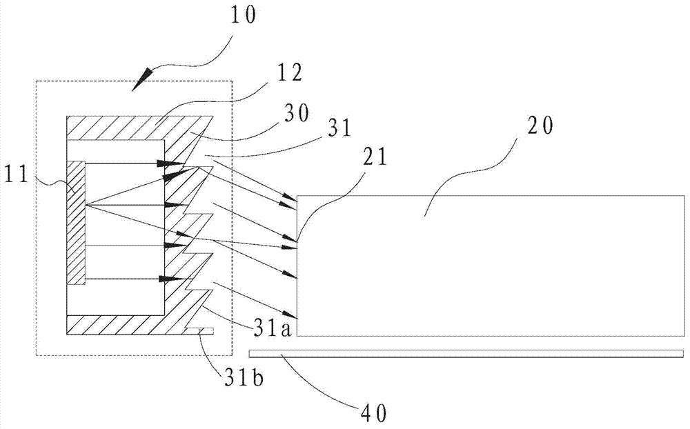
[0022] refer to figure 1 The ultra-thin surface light source device of the present invention includes an LED light source 10 and a light guide plate 20. The LED light source 10 includes a light-emitting chip 11 at the base and a transparent sealant 12 that seals the light-emitting chip 11. The light-incident side of the LED light source 10 and the light guide plate 20 21 opposite to each other, a polarizer 30 parallel to the light incident side 21 of the light guide plate 20 for projecting the light emitted by the light-emitting chip 11 toward the light guide plate 20 is provided between the light emitting chip 11 and the light guide plate 20 .

[0023] Specifically, the surface of the polarizer 30 opposite to the light guide plate 20 (that is, the surface facing the light incident side 21 in the figure) is provided with a plurality of sawtooth grooves 31 arranged longitudinally, and each sawtooth groove 31 includes an upper upper sawtooth surface 31a and the lower serrated su...

Embodiment 2

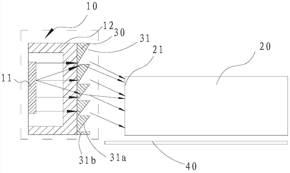
[0027] Such as figure 2 As shown, the only difference between this embodiment and Embodiment 1 is that the polarizer 30 is fixed on the sealant 12 and is in close contact with the outer surface of the sealant 12 . The polarizer 30 is specifically an optical film, and can be specifically arranged on the outer surface of the glue seal 12 by pasting.

Embodiment 3

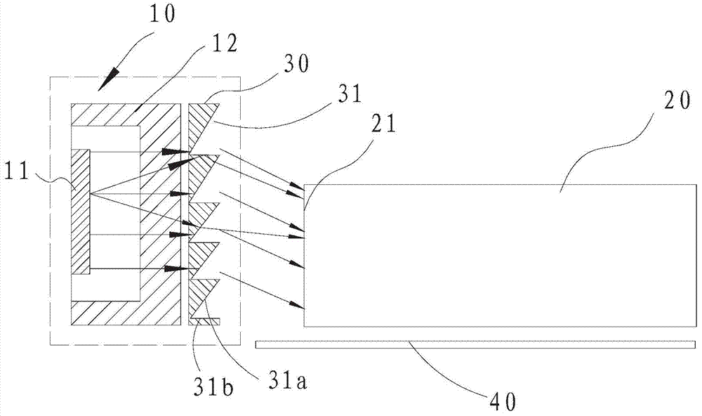
[0029] Such as image 3 As shown, the difference between this embodiment and Embodiment 1 is that the polarizer 30 is not in contact with the sealant 12 , but is arranged at intervals. Specifically, the polarizer 30 may be fixed on a corresponding structure of the display device, such as a plastic frame, an iron frame, and the like.

[0030] In the present invention, by setting the polarizer 30 between the light-emitting chip 11 and the light guide plate 20, the light emitted by the LED light source can be well controlled to be deflected within a certain angle range, and the light can be made without increasing the thickness of the light guide plate. All of them enter the light guide plate through the light incident side, which improves the utilization rate of light and is beneficial to the further thinning of the light guide plate and the surface light source device.


PUM


Abstract

The invention discloses an ultra-thin surface light source device. The ultra-thin surface light source device comprises an LED light source and a light guide plate; the LED light source comprises a lighting chip; the LED light source is arranged opposite to a light entering side of the light guide plate; a polarizing component, which is parallel to the guide plate to project light generated by the lighting chip to the light guide plate, is arranged between the lighting chip and the light guide plate. The ultra-thin surface light source device has the advantages that the light emitted by the LED light source can be controlled to polarize within a certain angle range; the light can completely enter the light guide plate through the light entering side on the premise that the thickness of the light guide plate is unchanged; therefore, the utilization rate of the light is improved; the light guide plate and the surface light source can be further thinned; meanwhile, a loudspeaker-shaped opening in the light entering side of the light guide plate can be saved, so that the manufacturing process of the light guide plate is simplified, and the cost can be decreased.

Description

technical field [0001] The invention relates to backlight display technology, in particular to an ultra-thin surface light source device. Background technique [0002] LED (Light Emitting Diode, that is, light-emitting diode) is a very competitive new energy-saving light source, which has a tendency to gradually replace traditional lighting sources. It has many advantages such as high luminous efficiency, good light quality, high color purity, suitable voltage, low power consumption and long service life. The backlight source is the light source for the LCD Liquid Crystal Display (LCD) panel. It is mainly composed of a light source, a light guide plate, an optical film, and a plastic frame. The backlight source needs to have high brightness, long life, and uniform light emission. LEDs are widely used in LCD backlights due to their many advantages. [0003] At present, due to the introduction of the concept of ultra-thin LCD, most of them are edge-lit LCDs, which use light ...

Claims


Application Information

Patent Timeline
IPC IPC(8): G02F1/13357
CPCG02B6/0025G02F1/133603G02F1/133615G02F1/133607
Inventor 陈玲艳
Owner SHENZHEN CHINA STAR OPTOELECTRONICS TECH CO LTD
Features
  • R&D
  • Intellectual Property
  • Life Sciences
  • Materials
  • Tech Scout
  • Unparalleled Data Quality
  • Higher Quality Content
  • 60% Fewer Hallucinations
Learn More