Energy-saving environmental-friendly electrical equipment box dehumidifying apparatus

An electrical equipment box, energy saving and environmental protection technology, applied in the direction of humidity control, non-electric variable control, control/regulation system, etc., can solve the problems of electrical equipment loss, short circuit, poor sealing quality, etc., to save resources, reduce production costs, Construct simple effects

Inactive Publication Date: 2015-04-08
STATE GRID CORP OF CHINA +3
View PDF6 Cites 6 Cited by
  • Summary
  • Abstract
  • Description
  • Claims
  • Application Information

AI Technical Summary

Problems solved by technology

[0002] The existing equipment boxes such as mechanism boxes, terminal boxes, distribution boxes, communication signal boxes, inspection and maintenance distribution boxes, protection terminal boxes, fire alarm boxes, etc. Substation mechanism boxes, terminal boxes, distribution boxes, and on-site electrical equipment boxes frequently enter water, causing electrical equipment tripping and direct economic losses. Spring rain, substation mechanism boxes, terminal boxes, distribution boxes, on-site electrical equipment boxes, etc. have poor sealing quality and seepage of rainwater to the terminal block or excessive water accumulation at the bottom of electrical equipment or large rainwater humidity in the wiring. The surface of the row is damp and causes short circuit or ground loss. Frequent circuit breaker trips and electrical equipment alarms cause large-scale power outages. If you want to deal with the leakage of electrical equipment wiring drains, you need to invest a lot of manpower, material resources, and financial resources.

Method used


Image

  • Energy-saving environmental-friendly electrical equipment box dehumidifying apparatus

Examples


Embodiment Construction

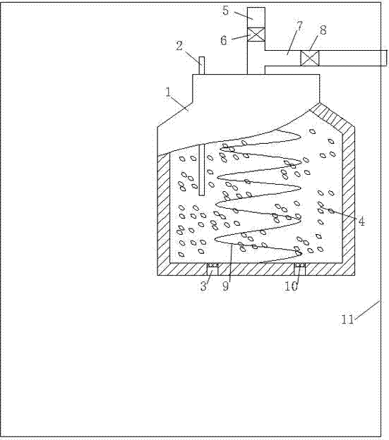
[0010] In order to make the above-mentioned features and advantages of the present invention more comprehensible, the following specific embodiments are described in detail with reference to the accompanying drawings.

[0011] refer to figure 1 , the present invention relates to an energy-saving and environment-friendly dehumidification device for an electrical equipment box, comprising a dehumidification tank 1 arranged in an electrical equipment box body 11, a plurality of ventilation holes 3 are provided at the bottom of the dehumidification tank, and the inside of the dehumidification tank is provided with a Silica gel particles 4 that absorb moisture in the air. The top of the dehumidification tank is provided with an air intake pipe 5 communicating with the air in the inner cavity of the electrical equipment box. The air intake pipe is provided with a first solenoid valve 6. The air inlet pipe of the dehumidification tank is also connected with a moisture discharge pipe ...


PUM


Abstract

The invention relates to an energy-saving environmental-friendly electrical equipment box dehumidifying apparatus. The apparatus comprises a dehumidifying pot arranged in an electrical equipment box body, and is characterized in that the bottom of the dehumidifying pot is provided with a plurality of through holes, the dehumidifying pot is internally provided with hygroscopic agent moisture silica gel particles for absorbing moisture in air, the top portion of the dehumidifying pot is provided with an air inlet pipe communicating with the air passage of the inner cavity of the electrical equipment box body, the air inlet pipe is provided with a first solenoid valve, a moisture discharge pipe is also connected with the air inlet pipe of the dehumidifying pot beside the air inlet pipe, the moisture discharge pipe is provided with a second solenoid valve, and the dehumidifying pot is also internally provided with an electric heating helix tube which is embedded in the hygroscopic agent silica gel particles absorbing the moisture in the air. According to the invention, the construction is simple, the realization is convenient, and the hygroscopic agent absorbing the moisture in the air can effectively absorb the moisture in the electrical equipment box body and has a repeated application characteristic. Besides, the apparatus reduces resources, decreases the production cost and reduces damage caused by a silica gel to a surrounding environment.

Description

technical field [0001] The invention relates to an energy-saving and environment-friendly dehumidification device for electrical equipment boxes, which is applied to the field of energy-saving and environment-friendly dehumidification and drying of equipment in various industries across the country. Background technique [0002] The existing equipment boxes such as mechanism boxes, terminal boxes, distribution boxes, communication signal boxes, inspection and maintenance distribution boxes, protection terminal boxes, fire alarm boxes, etc. Substation mechanism boxes, terminal boxes, distribution boxes, and on-site electrical equipment boxes frequently enter water, causing electrical equipment tripping and direct economic losses. Spring rain, substation mechanism boxes, terminal boxes, distribution boxes, on-site electrical equipment boxes, etc. have poor sealing quality and seepage of rainwater to the terminal block or excessive water accumulation at the bottom of electrical...

Claims


Application Information

Patent Timeline
Patent Type & Authority Applications(China)
IPC IPC(8): G05D22/02
Inventor 吴元晖
Owner STATE GRID CORP OF CHINA
Why Eureka
Try Eureka