
Induction furnace water temperature constant automatic control system and method

An automatic control system and constant water temperature technology, which is applied in the direction of control/regulation system, temperature control, non-electric variable control, etc., can solve the problems that the water temperature system cannot be automatically controlled, the service life of the heating furnace is affected, and the cooling effect of the furnace shell is not good. , to achieve the effect of automatic control of the induction furnace water temperature, which is conducive to large-scale popularization and use, and has a simple structure

Active Publication Date: 2015-04-08
ZHONGTIAN TECH FIBER OPTICS +1
View PDF10 Cites 5 Cited by
  • Summary
  • Abstract
  • Description
  • Claims
  • Application Information

AI Technical Summary

Problems solved by technology

[0004] At present, the temperature of the induction furnace during the heating process reaches thousands of degrees, and the inside of the heating furnace shell needs to be cooled by cooling water. Too large, easy to deform, long-term flow is too small, the cooling effect of the furnace shell is not good, affecting the service life of the heating furnace), generally add a cooling water flow meter in the cooling water channel to monitor the cooling water flow
But now generally only the flow of water can be controlled, but the water temperature system of the water cycle cannot be automatically controlled. Therefore, we need to automatically control the water temperature of the induction furnace under the condition that the process is stable and there is no control lag.

Method used


Image

  • Induction furnace water temperature constant automatic control system and method
  • Induction furnace water temperature constant automatic control system and method
  • Induction furnace water temperature constant automatic control system and method

Examples


Embodiment Construction

[0037] The implementation of the present invention will be illustrated by specific specific examples below, and those skilled in the art can easily understand other advantages and effects of the present invention from the contents disclosed in this specification.

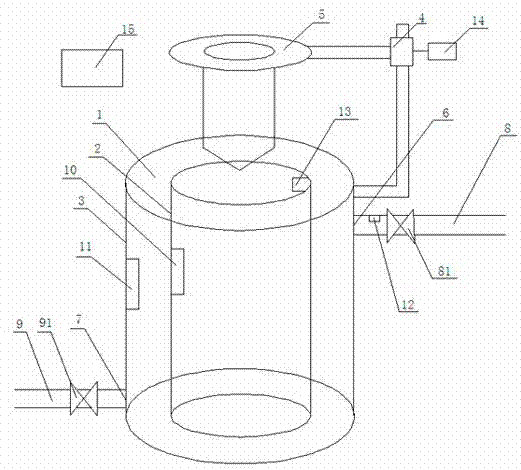
[0038] The present invention discloses an automatic control system for constant water temperature of an induction furnace. The system includes an induction furnace body 1. The induction furnace body 1 includes an outer cylinder 3 and an inner cylinder 2 embedded in the outer cylinder 3. The specific structure is as follows:

[0039] A chuck 5 is fixed directly above the induction furnace body 1 through a rod feeder 4, one end of the rod feeder 4 is fixedly connected to the chuck 5, the other end of the rod feeder 4 is fixedly connected to the outer wall of the outer cylinder 3, and the rod feeder 4 and The chuck 5 is a conventional technical structure in the technical field, so it will not be repeated here. The chuc...


PUM


Abstract

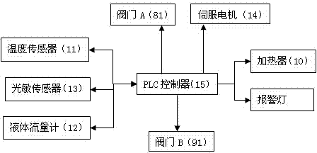
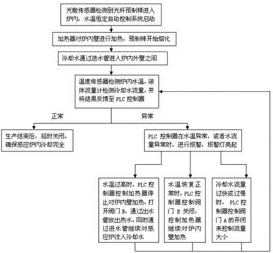
The invention discloses an induction furnace water temperature constant automatic control system comprising an induction furnace body which has a hollow cylindrical structure comprising an internal cylinder and an external cylinder. A bar-delivering device is fixed at the side surface of the external cylinder. A clamping disc is fixedly installed on the bar-delivering device. The clamping disc is arranged exactly above the induction furnace body. The side surface of the top part of the external cylinder is communicated with a water inlet pipe and a water outlet pipe. The water inlet pipe and the water outlet pipe are respectively provided with a valve A and a valve B. The system also comprises a heater, a temperature sensor, a liquid flow meter and a photosensitive sensor. Besides, the valve A and the valve B are connected with a PLC controller. The invention also discloses a control method of the induction furnace water temperature constant automatic control system. With combined action of the heater, a temperature controller, the PCL controller, the temperature sensor, the liquid flow meter and the pipeline transmitting valves, the objective of induction furnace water temperature constant automatic control is realized so that the structure is simple, the technology is table, lagging is reduced and the effect is obvious, and thus the induction furnace water temperature constant automatic control system is beneficial for wide-range popularization and use in the optical fiber manufacturing industry.

Description

technical field [0001] The invention relates to the field of automatic control, in particular to one A constant water temperature automatic control system and method for an induction furnace. Background technique [0002] Temperature control systems are widely used in industrial manufacturing. In the manufacturing industry that requires induction furnace heating, the water temperature control of the induction furnace has a great impact on the process and the service life of the induction furnace. However, the heating system of the induction furnace has complex processes, variable parameters, large operating inertia, and control lag. Therefore, the induction furnace water temperature automatic control system has extremely high requirements on the temperature control regulator. [0003] In the prior art, PID control is generally used to adjust the temperature of the water circulation system. PID control has three control methods: proportional, integral and differential, and...

Claims


Application Information

Patent Timeline
IPC IPC(8): G05D23/22
Inventor 蒋小龙张帆朱刘盅贾泽峰江金金苏海燕薛驰刘志忠曹珊珊
Owner ZHONGTIAN TECH FIBER OPTICS
Learn More