Quick scattering correction method for cone beam CT (Computed Tomography) image domain

A CT image, fast technology, applied in the field of medical engineering, can solve problems that cannot be used as a general algorithm, and achieve the effect of fast correction speed and high precision

Active Publication Date: 2015-04-08
ZHEJIANG UNIV
View PDF3 Cites 6 Cited by
  • Summary
  • Abstract
  • Description
  • Claims
  • Application Information

AI Technical Summary

Problems solved by technology

This type of method can effectively maintain patient information in cone beam CT, but it needs to use the existing planned CT images to realize the mapping, which cannot become a general algorithm

Method used


Image

  • Quick scattering correction method for cone beam CT (Computed Tomography) image domain
  • Quick scattering correction method for cone beam CT (Computed Tomography) image domain
  • Quick scattering correction method for cone beam CT (Computed Tomography) image domain

Examples


Embodiment Construction

[0055] The present invention will be described in detail below with reference to the drawings and specific embodiments.

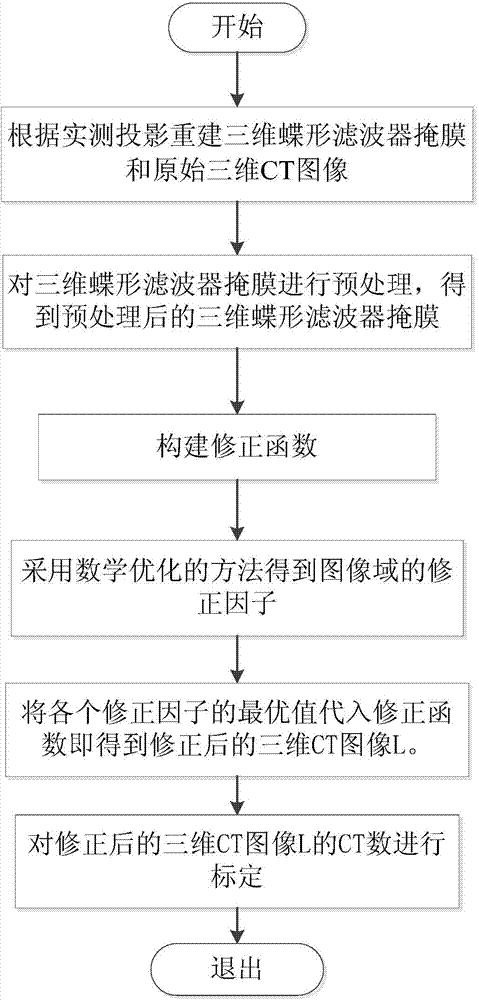
[0056] figure 1 It is a flow chart of the method for fast scattering artifact correction in the cone beam CT image domain of the present embodiment, including the following steps:

[0057] (1) Using the filtered back projection algorithm to reconstruct the original three-dimensional CT image and the three-dimensional butterfly filter mask according to the measured projection: the original three-dimensional CT image includes m layers of two-dimensional CT images, and the described three-dimensional butterfly filter mask includes m layers 2D butterfly filter mask;

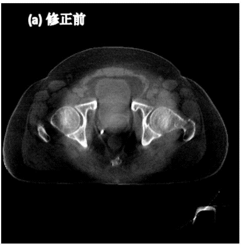
[0058] In this embodiment, m=200, and the obtained two-dimensional CT image in the original three-dimensional CT image is shown in FIG.

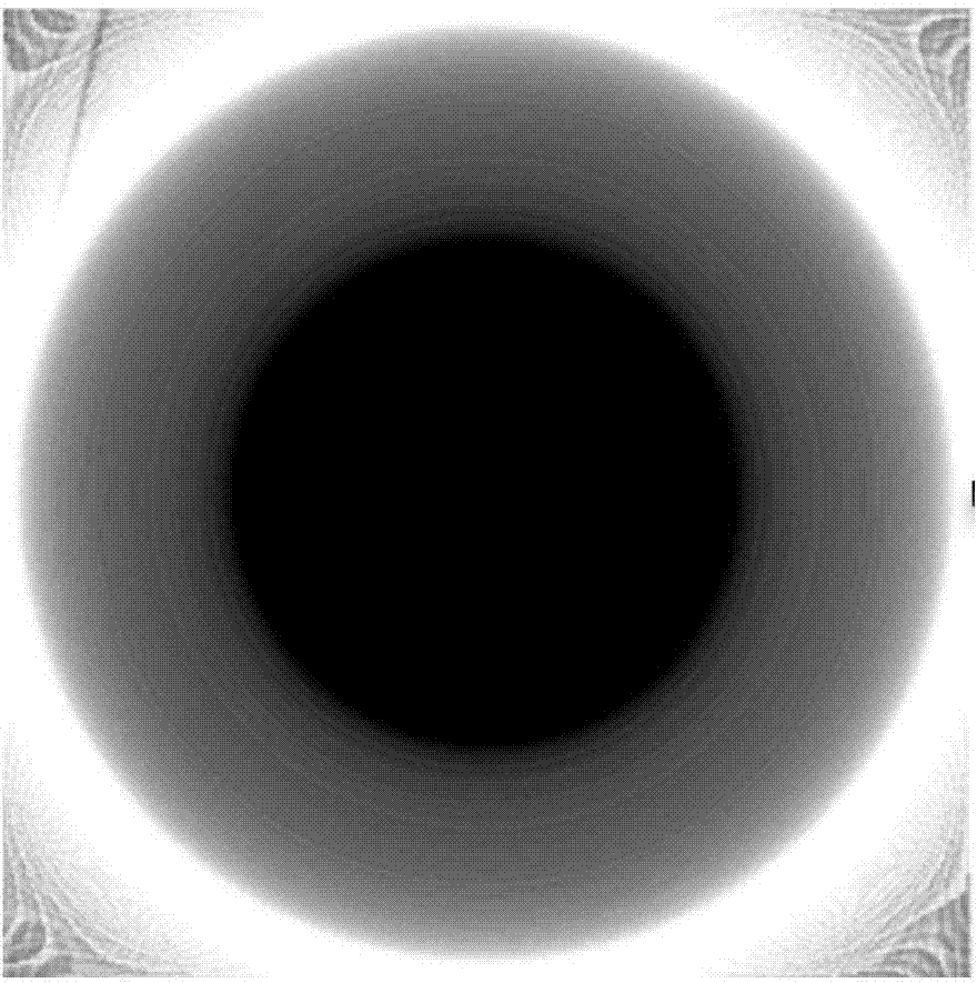
[0059] The two-dimensional butterfly filter mask in the three-dimensional butterfly filter mask of this embodiment is shown in FIG. 2( b ).

[0060] In this ...


PUM


Abstract

The invention discloses a quick scattering correction method for a cone beam CT (Computed Tomography) image domain. The quick scattering correction method comprises the following steps of adopting a filtering back-projection algorithm to reconstruct a three-dimensional butterfly filter mask and an original three-dimensional CT image according to actual-measurement projection, wherein the original three-dimensional CT image comprises m layers of two-dimensional CT images, and the three-dimensional butterfly filter mask comprises m layers of butterfly filter masks; setting a correction factor by aiming at each layer of three-dimensional CT image, and constructing a correction function based on the correction factors, the three-dimensional butterfly filter mask and the original three-dimensional CT images for correcting the original three-dimensional CT image; constructing an optimization function by aiming at the correction factors, wherein the optimization function comprises an optimization target function and an optimization constraint function; solving the optimization function to obtain an optimal value of each correction factor, and substituting the optimal value of the correction factor into the optimization function to obtain the corrected three-dimensional CT images. The quick scattering correction method for the cone beam CT image domain has the advantages of high precision of correction result and high correction speed.

Description

technical field [0001] The invention relates to the technical field of medical engineering, in particular to a rapid scattering correction method in cone-beam CT image domain. Background technique [0002] Current scatter corrections can be implemented in the projective domain or in the image domain. Scattering correction in projected domain is a traditional method. According to the characteristic that the scattering signal belongs to additive pollution and presents low-frequency distribution in space, the scattering distribution is estimated by measurement, simulation or analytical calculation, and then subtracted from the measured total signal to obtain the scattering Corrected projection. The corrected projection can use standard CT reconstruction algorithms, such as filtered back projection, to reconstruct a three-dimensional object. It mainly includes the following methods: reducing the solid angle of the detector to the light source (that is, increasing the air gap m...

Claims


Application Information

Patent Timeline
Patent Type & Authority Applications(China)
IPC IPC(8): G06T5/00
Inventor 牛田野吴蓬威
Owner ZHEJIANG UNIV
Why Eureka
Try Eureka