Permanent magnet slip clutch and control method

A clutch and permanent magnet technology, which is applied in the field of permanent magnet slip clutch and control, can solve the problems of low power density, large reactive power loss, and difficult control of permanent magnet slip clutch, so as to improve power density and improve Efficiency and enhancement of output speed characteristics

Active Publication Date: 2017-09-12
JIANGSU UNIV
View PDF3 Cites 0 Cited by
  • Summary
  • Abstract
  • Description
  • Claims
  • Application Information

AI Technical Summary

Problems solved by technology

[0005] Aiming at the problems of low power density and large reactive power loss of the electromagnetic slip clutch, the present invention proposes a permanent magnet slip clutch. In order to solve the problem of difficult control of the permanent magnet slip clutch, the present invention proposes a corresponding control method

Method used


Image

  • Permanent magnet slip clutch and control method
  • Permanent magnet slip clutch and control method
  • Permanent magnet slip clutch and control method

Examples


Embodiment Construction

[0041] The present invention will be further described below in conjunction with the accompanying drawings and implementation examples.

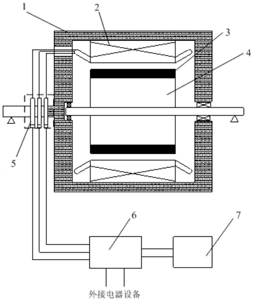
[0042] figure 1 It is a schematic diagram of the permanent magnet slip clutch. The permanent magnet slip clutch consists of an outer rotor 1 , an inner rotor 4 , a three-phase winding brush 5 , an energy recovery device 6 and a controller 7 . The rotating shaft of the outer rotor 1 is supported on the base of the slip clutch through bearings, and the rotating shaft of the inner rotor 4 is supported inside the rotating shaft of the outer rotor through bearings. The lead wires of the three-phase winding 2 are connected with the brushes 5 of the three-phase winding. The inner rotor poles 3 are placed on the surface of the inner rotor 4, and the magnetic force lines formed by the inner rotor poles 3 pass through the inner rotor 4, the air gap of the outer rotor 1 and the iron cores of the inner and outer rotors to form a closed loop. The ener...


PUM


Abstract

The invention relates to a permanent magnet slip clutch and a control method. The permanent magnet slip clutch includes outer rotor, inner rotor, three-phase winding brush, energy recovery device and controller; the energy recovery device recovers the slip loss generated in the three-phase winding, and can be connected to other electrical equipment; the controller controls The on-off of each MOS tube in the energy recovery device. The control method is to control the output of each signal with the goal of coordinating the speed regulation performance and recovery performance of the permanent magnet slip clutch. The invention improves the power density of the slip clutch, reduces the moment of inertia of the output shaft, improves responsiveness, and improves efficiency; the proposed control method improves the power factor of the recovery device and reduces the torque of the slip clutch fluctuations, which enhance the output speed characteristics of the permanent magnet slip clutch.

Description

technical field [0001] The invention relates to the field of power transmission, in particular to a permanent magnet slip clutch and a control method. Background technique [0002] Electromagnetic Slipping Clutch (EMSC for short), also known as electromagnetic slipping clutch, is widely used for its advantages of compact structure, no mechanical wear, convenient control, small current, and infinitely variable speed, especially in Some occasions where power sources cannot be applied, such as construction machinery, automobiles, ships and other fields. [0003] The EMSC is mainly composed of an outer rotor and an inner rotor. Generally, the outer rotor is an armature, and the inner rotor is an excitation winding. When the prime mover drives the inner rotor to rotate, the magnetic field formed by the excitation winding induces an electromotive force in the armature, generating eddy currents, which generate torque under the action of the magnetic field to drive the outer rotor ...

Claims


Application Information

Patent Timeline
Patent Type & Authority Patents(China)
IPC IPC(8): H02K49/10H02K49/04H02P21/00H02P21/14
Inventor 唐斌江浩斌耿国庆夏磊尧骏赵回邵凯
Owner JIANGSU UNIV
Why Eureka
Try Eureka