Particle manipulation system with out-of-plane channels

A technology for manipulating systems and particles, applied in the field of systems for manipulating small particles, can solve problems such as loss of function, cell damage, unavailability, etc., and achieve the effect of improving sorting speed and accuracy, and fast actuation speed

Active Publication Date: 2018-04-06
OWL BIOMEDICAL
View PDF9 Cites 0 Cited by
  • Summary
  • Abstract
  • Description
  • Claims
  • Application Information

AI Technical Summary

Problems solved by technology

Problems associated with these systems are cell damage or loss of function due to decompression, difficult and expensive disinfection procedures between samples, inability to subpopulate subpopulations according to different parameters, and owning, operating and maintaining these large and expensive Extensive training required for equipment components
For at least these reasons, the use of flow cytometry has been limited to large hospitals and laboratories, and the technology is not yet available to smaller entities

Method used


Image

  • Particle manipulation system with out-of-plane channels
  • Particle manipulation system with out-of-plane channels
  • Particle manipulation system with out-of-plane channels

Examples


Embodiment Construction

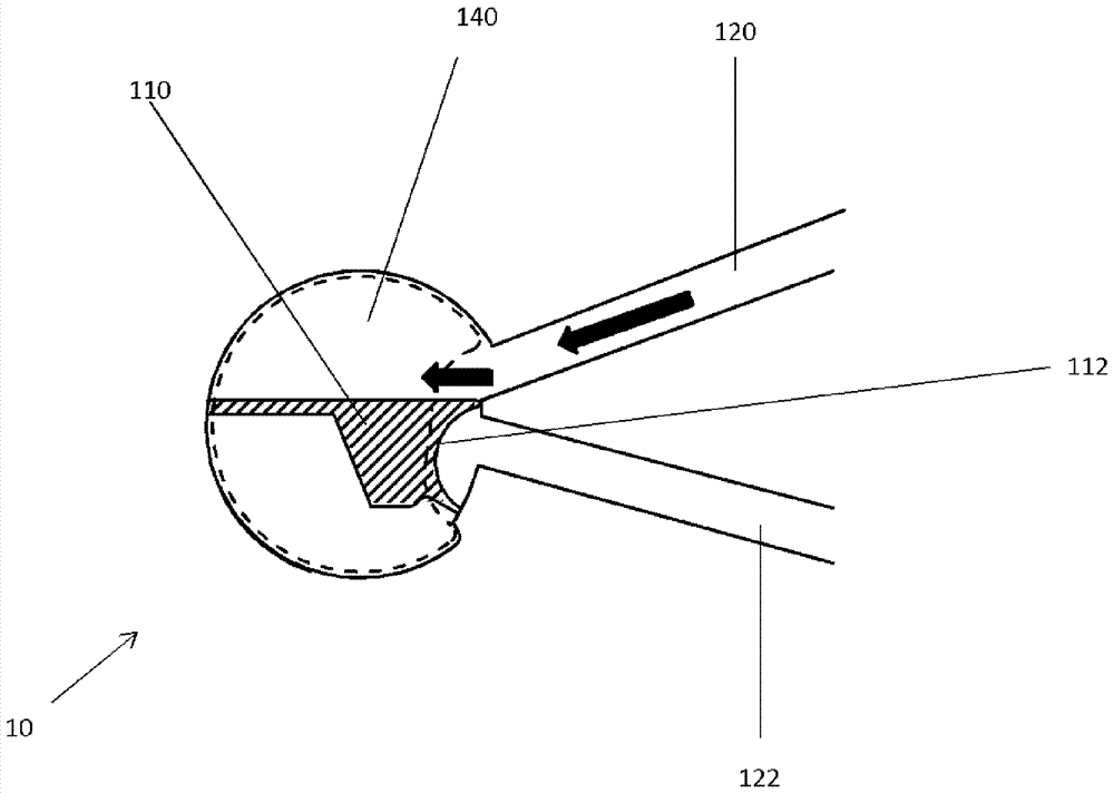
[0028] The system described herein is a particle sorting system that can utilize the microchannel configuration of a MEMS particle manipulation system. More generally, the systems and methods describe a particle manipulation system having an inlet channel and a plurality of output channels, wherein at least one of the plurality of output channels is disposed in a different plane than the inlet channel. This configuration has some significant advantages over the prior art.

[0029] In the figures discussed below, like reference numerals are intended to refer to like structures, and these structures are shown at various levels of detail to provide a clear view of the important features of the novel device. It should be understood that these figures do not necessarily depict structures to scale, and that directional designations such as "top," "bottom," "upper," "lower," "left," and "right" are arbitrary, as the device may be Constructed and operated in any particular orientatio...


PUM


Abstract

A particle manipulation system uses a MEMS-based microfabricated particle manipulation device having an inlet channel, an output channel, and a movable member formed on a substrate. The movable member moves parallel to the fabrication plane, like a fluid flowing in the inlet channel. The movable member separates the target particle from the rest of the particle, diverting it into the output channel. However, at least one output channel is not parallel to the fabrication plane. The device can be used to separate target particles from non-target materials in a sample stream. Target particles can be, for example, stem cells, fertilized eggs, cancer cells, T cells, components of blood, bacteria or DNA samples. The particle manipulation system may also include microfluidic structures that focus particles of interest in specific portions of the inlet channel.

Description

technical field [0001] The present invention relates to systems and methods for manipulating small particles in microfabricated fluidic channels. Background technique [0002] Microelectromechanical systems (MEMS) are very small, often movable structures fabricated on substrates using surface or bulk photolithographic processing techniques such as those used to fabricate semiconductor devices. MEMS devices can be, for example, movable actuators, sensors, valves, pistons or switches, with feature sizes of a few micrometers to hundreds of micrometers. For example, movable MEMS switches can be used to connect one or more input terminals to one or more output terminals, all microfabricated on the substrate. The actuation means for the movable switch can be eg thermal, piezoelectric, electrostatic or magnetic. MEMS devices can be fabricated on semiconductor substrates that can manipulate particles passing the MEMS device in a fluid stream. [0003] In another example, a MEMS d...

Claims


Application Information

Patent Timeline
Patent Type & Authority Patents(China)
IPC IPC(8): B01L3/00
CPCB01L3/502738B01L3/502761B01L2200/0652B01L2300/0654B01L2300/0864B01L2400/0622B01L2400/0633F16K99/0011F16K99/0013F16K99/0028F16K99/0046F16K2099/0084B01L3/502707B01L3/502715B01L2300/0627G01N15/1404G01N15/1484G01N21/6402G01N21/6428G01N21/6486G01N2015/149G01N2021/6439G01N2201/06113
Inventor N.马丁内斯K.卡兰达尔K.希尔兹K.特纳S.米尔腾依J.福斯特
Owner OWL BIOMEDICAL
Why Eureka
Try Eureka