Pipe flow section device applicable to mineralized fine grain minerals

A mineral and pipe flow technology, applied in the direction of cyclone device, solid separation, flotation, etc., can solve the problems of fine mineral particle loss, increase equipment cost, increase the length of pipe flow section, etc., achieve enhanced mineralization effect and improve recovery Efficiency, the effect of increasing the probability of collision

Active Publication Date: 2015-04-15
CHINA UNIV OF MINING & TECH
View PDF6 Cites 10 Cited by
  • Summary
  • Abstract
  • Description
  • Claims
  • Application Information

AI Technical Summary

Problems solved by technology

[0003] The pipe flow section is the main place where refractory fine-grained minerals collide with and adhere to air bubbles during the flotation process of the cyclone-static micro-bubble flotation column. The turbulence intensity in this area determines the mineralization and recovery efficiency of fine particles. The pipeline structure used in the existing technology is a light pipe, and the turbulence intensity is low, which leads to the loss of a large number of fine mineral particles that have been dissociated in the tailings
In order to improve the turbulence intensity of the pipe flow section, there are two main methods: increasing the length of the pipe flow section or using a special-shaped pipe flow section (such as a U-shaped pipe flow section), but these two methods will cause serious wear of the pipe flow section and affect the Device Stability
Increasing the length of the pipe flow section will, on the one hand, increase the height of the cyclone-static microbubble flotation column and increase the equipment cost; on the other hand, a longer pipe flow section has no effect on increasing the maximum turbulence intensity inside the pipe significantly

Method used


Image

  • Pipe flow section device applicable to mineralized fine grain minerals
  • Pipe flow section device applicable to mineralized fine grain minerals
  • Pipe flow section device applicable to mineralized fine grain minerals

Examples


Embodiment Construction

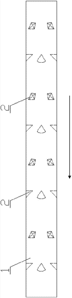
[0020] The present invention will be further described below in conjunction with accompanying drawing. figure 1 The arrows in represent the flow direction.

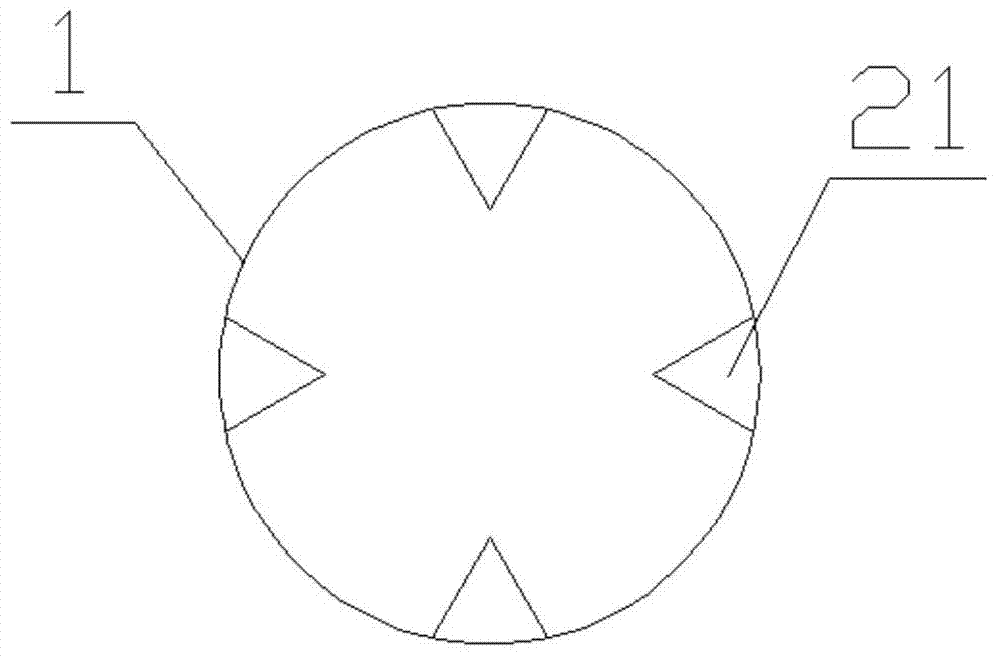
[0021] like Figure 1 to Figure 2 As shown, the pipeline 1 comprising the bubble generator downstream of the flotation column to the inlet end of the swirl section is provided with at least one row of vortex generators 2 on the inner wall of the pipeline 1 along the axis of the pipeline, and the vortex generators It is several protrusions 21 surrounding the inner pipe wall of the pipeline.

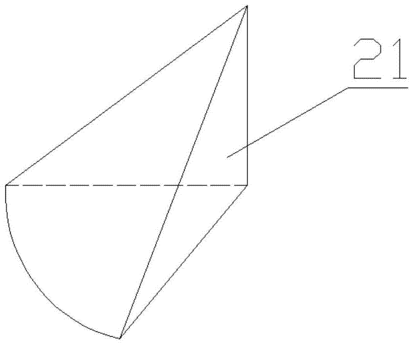
[0022] The preferred solution is as image 3 As shown, the protrusion 21 has a tetrahedral structure, and the surface of the tetrahedron connected with the inner pipe wall of the pipeline 1 is the bottom surface.

[0023] Further, the ratio of the height between the vertices of the tetrahedron and the bottom surface to the inner diameter of the pipeline 1 is 0.15˜0.3.

[0024] Furthermore, the bottom of the tetrahedron is an isosc...


PUM


Abstract

The invention discloses a pipe flow section device applicable to mineralized fine grain minerals. The device comprises a pipeline (1) between the downstream of a bubble generator of a flotation column and an inlet end of a rotating flow inlet end, wherein the inner pipe wall of the pipeline (1) along the inner pipe wall of a pipeline axis is provided with at least a row of vortex generators (2), and the vortex generators are a plurality of protuberances (21) surrounding the inner pipe wall. The vortex generator in the pipe can be changed by the vortex generator set in the pipeline, therefore the collision probability between mineral grains and bubbles can be improved, the turbulence intensity in the pipe can be gradually enhanced, the mineral effect can be enhanced, and the recovery ratio of the fine minerals can be improved.

Description

technical field [0001] The invention relates to a pipe flow section device, in particular to a pipe flow section device suitable for the mineralization of fine-grained minerals, and belongs to the technical field of mineral processing. Background technique [0002] The cyclone-static micro-bubble flotation column is used in the flotation of lean and fine minerals. It consists of a column flotation unit, a cyclone separation unit and a tube flotation unit. The column flotation unit is used for pre-selection of minerals. Good minerals are preferentially flotation to obtain high-quality concentrates; the cyclone separation unit further separates the medium ore, and obtains qualified tailings through high recovery capacity; the tube flotation unit is located behind the bubble generator and has a built-in In the pipe flow section before the cyclone, the fluid in the pipe flow section enters the cyclone separation section at a high energy state along the tangential direction at a ...

Claims


Application Information

Patent Timeline
Patent Type & Authority Applications(China)
IPC IPC(8): B03D1/02B03D1/14B04C9/00
Inventor 王利军闫小康贾彦王铖健刘刚王爱
Owner CHINA UNIV OF MINING & TECH
Why Eureka
Try Eureka