Floor machining center ram

A machining center, floor-standing technology, used in metal processing equipment, metal processing mechanical parts, manufacturing tools, etc., can solve the problems of limited range of bearing capacity, difficult to achieve precision machining, low machining accuracy, etc., to ensure long-term stable work. , The effect of enhancing force performance and high machining accuracy

Active Publication Date: 2015-04-15
昆山华都精工精密机械股份有限公司
View PDF8 Cites 2 Cited by
  • Summary
  • Abstract
  • Description
  • Claims
  • Application Information

AI Technical Summary

Problems solved by technology

[0002] With the continuous advancement of machining technology, machined parts are becoming more and more complex, and the size of parts is also increasing. Some traditional machining equipment have good machining accuracy, but their range of action and load-bearing capacity are limited, making it difficult to process. Large size and heavy workpieces
Some equipment can process large-size and heavy-weight workpieces, but the processing accuracy is not high, and it is difficult to achieve precision machining
[0003] Therefore, traditional mechanical processing equipment is difficult to meet the needs of workpiece processing in some fields, and it is urgent to provide a high-precision processing equipment for large workpieces.

Method used


Image

  • Floor machining center ram
  • Floor machining center ram
  • Floor machining center ram

Examples


Embodiment Construction

[0026] The technical solutions of the present invention will be further described below in conjunction with the accompanying drawings and through specific implementation methods.

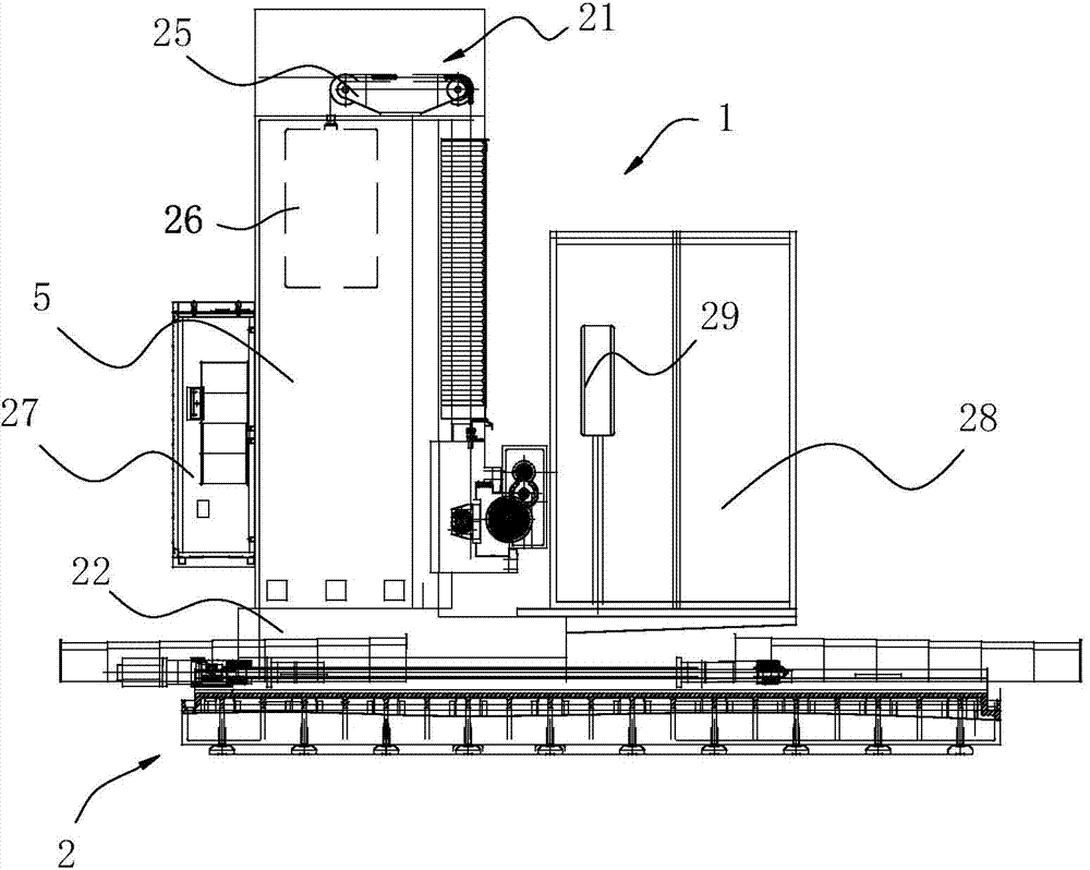
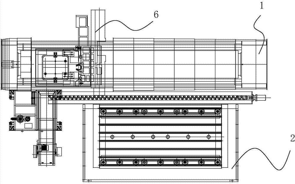
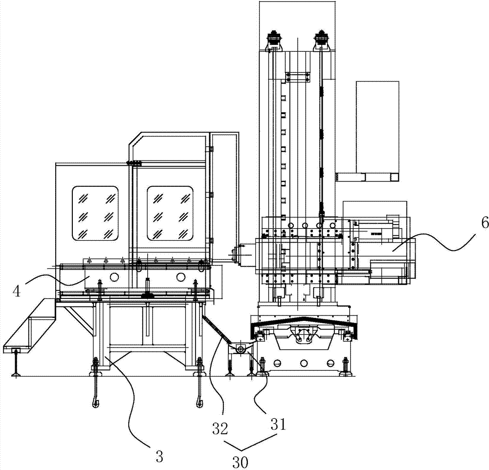
[0027] like Figure 1-6 As shown, in this embodiment, a floor-standing horizontal machining center of the present invention includes a tool installation platform 1 and a workpiece installation platform 2 arranged side by side and installed on the ground respectively. The workpiece installation platform 2 includes a fixing seat 3 and a set On the workbench 4 on the fixed seat 3, the tool installation platform 1 is provided with a first moving track along the horizontal direction, and a column 5 is vertically arranged on the first moving track, and the column 5 can slide along the first moving track. There is a second moving track perpendicular to the first moving track, the second moving track is provided with a ram 6 for installing the main shaft 7, the main shaft 7 is installed in the ram 6, and th...


PUM


Abstract

The invention discloses a floor machining center ram. The ram comprise a spindle box, a gear box and a counter weight. The counter weight and the spindle box are in an integrated structure. A gear box mounting groove for mounting the gear box is formed between the spindle box and the counter weight. A through hole communicated with the spindle box is formed in one side of the gear box mounting groove close to the spindle box, and an upper sliding rail and a lower sliding rail for enabling the ram to slide in the sliding rail are arranged on the upper and lower sides of the gear box. The thicknesses of planes where the upper sliding rail and the lower sliding rail are disposed are different, and the upper sliding rail and the lower sliding rail are disposed in the different planes to form a triangular structure. By means of the ram, the ram stress performance can be improved effectively.

Description

technical field [0001] The invention relates to the technical field of mechanical processing, in particular to a floor type horizontal machining center ram. Background technique [0002] With the continuous advancement of machining technology, machined parts are becoming more and more complex, and the size of parts is also increasing. Some traditional machining equipment have good machining accuracy, but their range of action and load-bearing capacity are limited, making it difficult to process. Workpieces with large size and heavy weight. Some equipment can realize the processing of large-sized and heavy-weight workpieces, but the processing accuracy is not high, and it is difficult to achieve precision processing. [0003] Therefore, traditional mechanical processing equipment is difficult to meet the needs of workpiece processing in some fields, and it is urgent to provide a high-precision processing equipment for large workpieces. The ram is used as the installation st...

Claims


Application Information

Patent Timeline
Patent Type & Authority Applications(China)
IPC IPC(8): B23Q1/25B23Q1/26
CPCB23Q1/25B23Q1/26
Inventor 向彬
Owner 昆山华都精工精密机械股份有限公司
Why Eureka
Try Eureka