

Power clutch device
A clutch device and power technology, which is applied in the direction of mechanically driven clutches, clutches, threshing equipment, etc., can solve the problems of shortening the service life of the power output mechanism, increasing the user's labor, and man-made food loss and waste, so as to facilitate operation and increase work. Time and labor reduction effect
- Summary
- Abstract
- Description
- Claims
- Application Information
AI Technical Summary
Problems solved by technology
Method used
Image

Examples
Embodiment 1
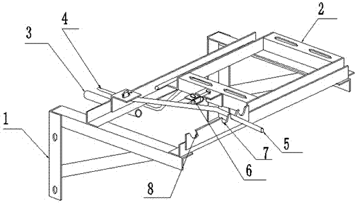
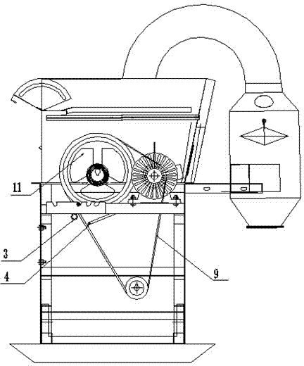
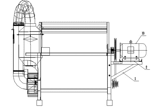
[0044] This embodiment includes a power frame 1, an installation body 2, a fixed rod 3 and a movable rod 4, the installation body 2 is installed on the power frame 1, and can slide on the power frame 1, and the fixed rod 3 is installed on the power frame 1, the movable rod 4 is connected to the installation body 1, when the installation body 2 slides on the power frame 1, the movable rod 4 approaches or moves away from the fixed rod 3, so as to realize the clamping and loosening of the belt 9 and complete the rotation of the thresher The clutch of the shaft 11 and the power take-off mechanism 10 .
[0045] This embodiment is installed on the side of the threshing machine, the power frame 1 is welded or fixed on the side of the threshing machine by bolts, the power output mechanism 11 is installed on the mounting body 2, and the belt 9 of the power output mechanism and the threshing mechanism is connected during installation Installed between the fixed rod 3 and the movable rod...
Embodiment 2
[0047] This embodiment includes a power frame 1, an installation body 2, a fixed rod 3 and a movable rod 4, the installation body 2 is installed on the power frame 1, and can slide on the power frame 1, and the fixed rod 3 is installed on the power frame 1, the movable rod 4 is connected to the installation body 1, when the installation body 2 slides on the power frame 1, the movable rod 4 approaches or moves away from the fixed rod 3, so as to realize the clamping and loosening of the belt 9 and complete the rotation of the thresher The clutch of the shaft 11 and the power take-off mechanism 10 .
[0048] This embodiment also includes a clutch control lever 5, one end of the clutch control lever 5 is fixed on the power frame 1 through a rotating shaft, the clutch control lever 5 is connected with the mounting body 2 through a movable joint 6, and the clutch control lever 5 drives the mounting body 2 on the power machine. Slide on shelf 1.
[0049] In this embodiment, by oper...
Embodiment 3
[0051] This embodiment includes a power frame 1, an installation body 2, a fixed rod 3 and a movable rod 4, the installation body 2 is installed on the power frame 1, and can slide on the power frame 1, and the fixed rod 3 is installed on the power frame 1, the movable rod 4 is connected to the installation body 1, when the installation body 2 slides on the power frame 1, the movable rod 4 approaches or moves away from the fixed rod 3, so as to realize the clamping and loosening of the belt 9 and complete the rotation of the thresher The clutch of the shaft 11 and the power take-off mechanism 10 .
[0052] This embodiment also includes a clutch control lever 5, one end of the clutch control lever 5 is fixed on the power frame 1 through a rotating shaft, the clutch control lever 5 is connected with the mounting body 2 through a movable joint 6, and the clutch control lever 5 drives the mounting body 2 on the power machine. Slide on shelf 1.
[0053] The power frame 1 is also p...
PUM
 Abstract
Description
Claims
Application Information