
Bistable electromagnetic actuating apparatus, armature assembly and camshaft adjustment apparatus

A technology of adjusting equipment and bistable state, which is applied in the direction of electromagnets, electrical components, mechanical equipment, etc., can solve the problems of narrow and unfavorable stroke areas, and achieve the effect of short switching time and large tolerance range

Active Publication Date: 2015-04-15
ETO MAGNETIC GMBH
View PDF12 Cites 8 Cited by
  • Summary
  • Abstract
  • Description
  • Claims
  • Application Information

AI Technical Summary

Problems solved by technology

[0005] This is disadvantageous in spring-supported bistable adjusting devices, since only a small part of the available magnet work is available for prestressing the spring, i.e. where sufficient permanent magnetic force is available for the adjusting element provided with the permanent magnet arrangement Narrow stroke area for automatic pull back to end position on core area side

Method used


Image

  • Bistable electromagnetic actuating apparatus, armature assembly and camshaft adjustment apparatus
  • Bistable electromagnetic actuating apparatus, armature assembly and camshaft adjustment apparatus
  • Bistable electromagnetic actuating apparatus, armature assembly and camshaft adjustment apparatus

Examples


Embodiment Construction

[0032] Identical elements and elements with the same function are denoted by the same reference numerals in the figures.

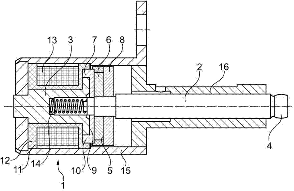
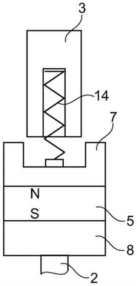
[0033] exist figure 1 shows an electromagnetic adjusting device 1 used in a camshaft adjusting device. The regulating device corresponds in its basic structure to the one in DE 201 114 466 U1 figure 1 The adjustment device shown in , therefore reference is made in general to this associated figure description, which is to be considered as expressly belonging to the disclosure content of the present application. A significant difference to adjusting devices according to the prior art is that the core region and the permanent magnet arrangement overlap axially in the core-side end position and do not work with a flat armature assembly as in the prior art.

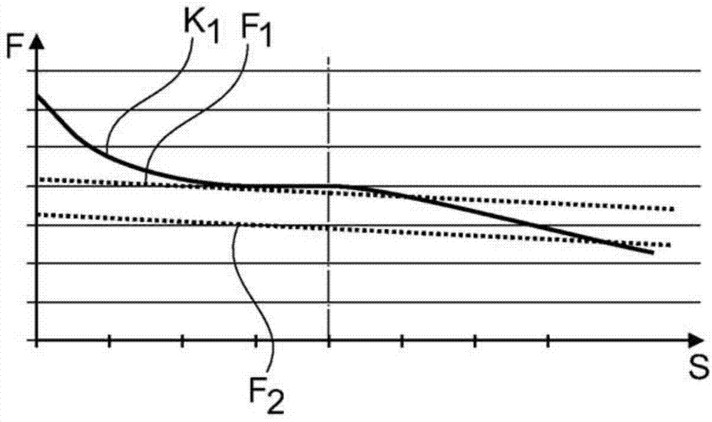
[0034] At the same time, the spring device is additionally dimensioned—in the embodiment shown here, the spring device preferably has a higher pretension and a lower spring constant. Details as follow:...


PUM


Abstract

The invention relates to a bistable electromagnetic actuating apparatus (1) having an actuating element (2), which forms an engagement region (4) at the end and can be moved axially between two end positions, in particular for engaging in a control groove in a cam of an internal combustion engine, and having a coil device (11) which is provided in a stationary manner relative to the actuating element (2) and is designed to exert a force on said actuating element, wherein the actuating element (2) has permanent-magnet means (5) which are designed to interact with a core region (3) which is provided in a stationary manner relative to the actuating element (2), and wherein the coil device (11) is designed to generate a counterforce, which counteracts a retaining force of the permanent-magnet means (5) and releases said permanent-magnet means from the core region (3), in response to an electronic actuation signal, and wherein spring means (14) are provided, said spring means being arranged such that they apply a spring force to the actuating element (2) in an axial direction which faces away from the core region (3). The invention makes provision for the core region (3) and the permanent-magnet means (5) to overlap in the axial direction for the purpose of influencing the retrieval point.

Description

technical field [0001] The invention relates to a bistable electromagnetic adjusting device according to the preamble of claim 1 , an armature assembly for an electromagnetic adjusting device according to the preamble of claim 9 and a camshaft adjusting device according to claim 10 . Background technique [0002] DE 201 14 466 U1 shows a bistable electromagnetic adjusting device for use in a camshaft adjusting device as described, for example, in DE 20 2009 011 804 U1. The known bistable electromagnetic adjusting device is characterized in that a permanent magnet arrangement is provided on the adjusting element, said permanent magnet arrangement comprising two pole disks and an axially magnetized permanent magnet ring in between. The permanent magnet arrangement interacts with the stationary core region to generate an attractive force, wherein the permanent magnet arrangement and the core region lie opposite each other in the core region-side end position. In this end posit...

Claims


Application Information

Patent Timeline
Patent Type & Authority Applications(China)
IPC IPC(8): H01F7/16F01L13/00H01F7/122
CPCH01F7/1646F01L2820/031F01L2013/0052F01L13/0036F01L13/0015H01F7/122
Inventor J.比尔斯纳P.范高尔P.文康
Owner ETO MAGNETIC GMBH
Learn More