Mechanical arm for clamping cans

A technology for manipulators and cans, which is applied in the direction of manipulators, program-controlled manipulators, chucks, etc., and can solve problems such as low efficiency

Inactive Publication Date: 2015-04-22
CHONGQING QINFA FOOD
View PDF0 Cites 34 Cited by
  • Summary
  • Abstract
  • Description
  • Claims
  • Application Information

AI Technical Summary

Problems solved by technology

[0003] In the process of processing and manufacturing, if individual cans need to be transferred automatically, it is usually used to transfer between the conveyor belt and various processing machinery. If manual transfer is used, the efficiency will inevitably be low

Method used


Image

  • Mechanical arm for clamping cans

Examples


Embodiment Construction

[0011] The present invention will be described in further detail below by means of specific embodiments:

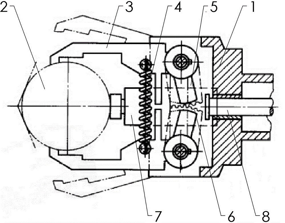
[0012] The reference numerals in the drawings of the description include: boom 1, can 2, arm claw 3, extension spring 4, rocking bar 5, sector gear 6, pressure rod 7, piston rod 8 of telescopic cylinder.

[0013] The embodiment is basically as attached figure 1 As shown: the arm frame is installed on the movable equipment, and the left and right sides of the arm frame are symmetrically hinged with arm claws for clamping the opposite side of the can, and a tension spring is connected between the two arm claws. The claws of the two arms mesh with each other through sector gears. The synchronization of rotation is better.

[0014] Through the dovetail groove, the arm frame is slidably connected with a pressure rod located in the middle of the symmetrical line of the two arm claws. The clamping part of the pressure rod is located between the two arm claws to correspond to t...


PUM


Abstract

The invention discloses a mechanical arm for clamping cans. The mechanical arm for clamping cans is used for transferring cans efficiently and stably. The mechanical arm for clamping cans comprises an arm frame. Arm claws are symmetrically hinged to the arm frame and used for clamping the opposite sides of the cans. The arm frame is connected with a pressing rod located on the symmetrical line of the two arm claws in a sliding mode. A clamping portion of the pressing rod is located between the two arm claws so as to correspond to the side walls of the cans. The two sides of the pressing rod are provided with limiting grooves respectively. Rocking bars fixedly connected to the two arm claws are embedded into the limiting grooves to be driven to rotate. A telescopic air cylinder is arranged beside a drive portion, opposite to the clamping portion, on the pressing rod, and a piston rod of the telescopic air cylinder is located on the symmetrical line of the two arm claws. According to the mechanical arm for clamping cans, the two arm claws and the clamping portion of the pressing rod can conduct three-point clamping on the cans at the same time, and stable clamping can be achieved, clamping and loosening of the arm claws can be controlled automatically, and the mechanical arm for clamping cans is very convenient to operate.

Description

technical field [0001] The invention relates to a can clamping manipulator. Background technique [0002] The domestic consumer market is taking off. The survey from the China National Food Industry Association shows that with the improvement of residents' living standards and the increasing travel and tourism, food consumption concepts and methods are quietly changing. Many families are trying to liberate themselves from the kitchen to reduce oil fume pollution and housework. Canned food is adapting to people's daily needs due to its convenience, sanitation and easy storage, and is increasingly popular. In addition, the consumption level of canned food in our country is still very low. In terms of per capita annual consumption, the United States is 90 kg, Western Europe is 50 kg, Japan is 23 kg, and my country is only 1 kg. It can be seen that the domestic market has not really started yet, and the potential is huge. [0003] In the process of processing and manufacturin...

Claims


Application Information

Patent Timeline
Patent Type & Authority Applications(China)
IPC IPC(8): B65G47/90B25J15/08B25J9/14
Inventor 龚东亚
Owner CHONGQING QINFA FOOD
Why Eureka
Try Eureka