Automatic yarn separating machine

A technology of automatic yarn splitter and yarn splitter bar, which is applied in the directions of skeining, textile, textile and papermaking, etc. It can solve the problems of visual fatigue, high labor intensity, and low production efficiency, achieve accurate and clear yarn splitting, and reduce labor costs. The effect of strength and simple structure

Active Publication Date: 2015-04-22
YONGXUSHENG MACHINERY TECH CHANGZHOU CO LTD
View PDF5 Cites 5 Cited by
  • Summary
  • Abstract
  • Description
  • Claims
  • Application Information

AI Technical Summary

Problems solved by technology

High labor intensity, visual fa

Method used


Image

  • Automatic yarn separating machine
  • Automatic yarn separating machine
  • Automatic yarn separating machine

Examples


Embodiment 1

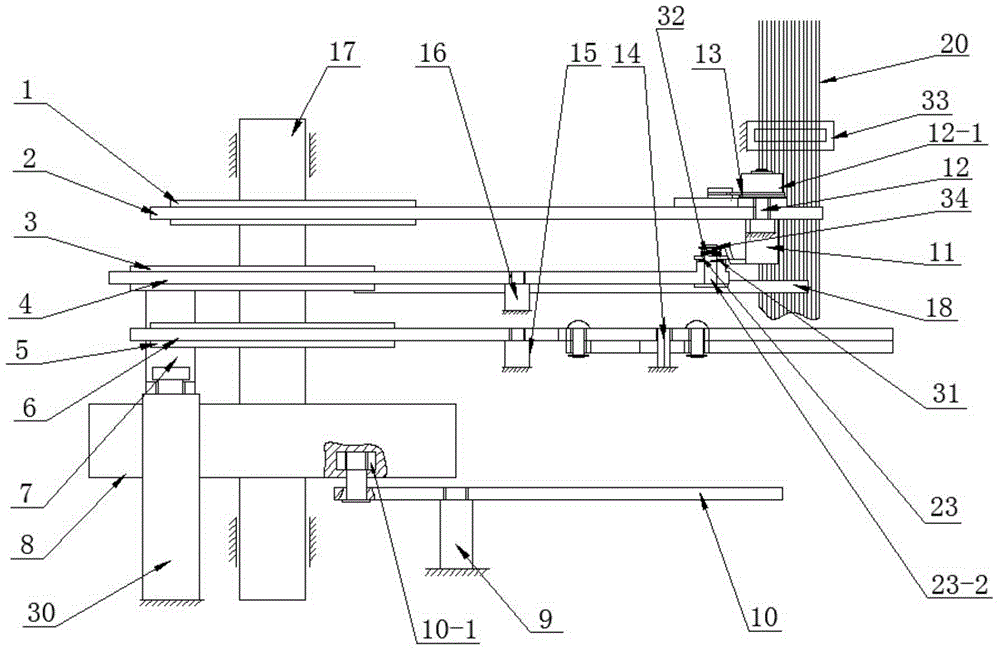
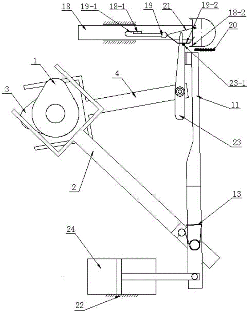
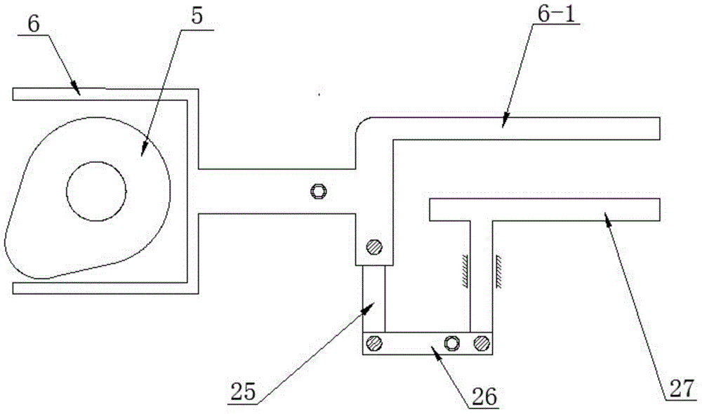
[0024] see Figure 1 to Figure 4 , The automatic yarn splitting machine of this embodiment includes a frame 22, a motor, a camshaft 17, an upper cam 1, a middle cam 3, a lower cam 5, an end cam 8, a limit mechanism, a yarn splitting mechanism, a yarn clamping mechanism, and a feeder Yarn mechanism.

[0025] The upper cam 1, the middle cam 3, the lower cam 5 and the end cam 8 are sequentially fixed on the cam shaft 17 from top to bottom, and the motor drives the cam shaft 17 to rotate. The limit mechanism, the yarn dividing mechanism, the yarn clamping mechanism and the yarn feeding mechanism are matched with the upper cam 1, the middle cam 3, the lower cam 5 and the end cam 8 respectively. The limit mechanism is used to limit the position of the yarn splitting mechanism. The yarn dividing mechanism pushes out a yarn at the foremost end on the weaving shaft yarn car. The yarn clamping mechanism stretches the yarn ejected from the yarn splitting mechanism. The yarn feeding mech...


PUM


Abstract

The invention discloses an automatic yarn separating machine which comprises a rack, a motor, a camshaft, an upper cam, a middle cam, a lower cam, an end face cam, a limiting mechanism, a yarn separating mechanism, a yarn clamping mechanism and a yarn feeding mechanism. The upper cam, the middle cam, the lower cam and the end face cam are sequentially fixed to the camshaft from top to bottom. The motor drives the camshaft to rotate. The limiting mechanism, the yarn separating mechanism, the yarn clamping mechanism and the yarn feeding mechanism are matched with the upper cam, the middle cam, the lower cam and the end face cam respectively. The limiting mechanism is used for limiting the position of the yarn separating mechanism. The yarn separating mechanism ejects out one piece of yarn located at the foremost end of a weaving shaft charka. The yarn clamping mechanism enables the yarn ejected out by the yarn separating mechanism to be tightened. The yarn feeding mechanism pushes the yarn ejected out by the yarn separating mechanism into a clamping opening. The warp yarn conveyed by the weaving shaft charka to be separated fast and automatically in sequence one by one and fed into the next warp yarn threading working procedure accurately, labor intensity is relieved, the labor cost is saved, and the production efficiency is improved.

Description

Technical field [0001] The invention relates to an automatic yarn dividing machine. Background technique [0002] The traditional yarn splitting is done manually. The two workers sat opposite each other, visually separating the thousands of yarns on the weaving shafts one by one, and then drawing them in. High labor intensity, visual fatigue and low production efficiency. Summary of the invention [0003] The purpose of the present invention is to provide an automatic yarn splitting machine, which reduces labor intensity, saves labor costs and improves production efficiency. [0004] The technical solution to achieve the purpose of the present invention is: an automatic yarn splitting machine, including a frame, a motor, a camshaft, an upper cam, a middle cam, a lower cam, an end cam, a limit mechanism, a yarn splitting mechanism, a yarn clamping mechanism and a feeder Yarn mechanism; the upper cam, the middle cam, the lower cam and the end cam are sequentially fixed on the camsh...

Claims


Application Information

Patent Timeline
IPC IPC(8): D02H9/00
CPCD03J1/13
Inventor 刘进球刘光新王磊庄伟
Owner YONGXUSHENG MACHINERY TECH CHANGZHOU CO LTD
Why Eureka
Try Eureka