Method for determining indicator diagram of electrical parameters of rod-pumped well

A technology for pumping wells and determination methods, which is applied to the automatic control system of drilling, drilling equipment, earthwork drilling and production, etc. It can solve problems such as difficult analysis process, and achieve practicality, simple and convenient practical measurement, and convenient and practical testing Effect

Active Publication Date: 2015-04-22
哈尔滨斯特凯峰电子有限公司
View PDF10 Cites 31 Cited by
  • Summary
  • Abstract
  • Description
  • Claims
  • Application Information

AI Technical Summary

Problems solved by technology

The actual load of the suspension point can be obtained by using the measured dynamometer diagram, which is used for the analysis (diagnosis) of the working conditions of the machine, rod and pump; around 1990, the ground dynamometer diagram was used to derive the downhole pump dynamometer diagram, and the downhole dynamometer diagram Figure deduces the daily liquid production rate of a single well. In the process, complex factors such as pump leakage, effective downhole stroke, gas content, and pump efficiency

Method used


Image

  • Method for determining indicator diagram of electrical parameters of rod-pumped well
  • Method for determining indicator diagram of electrical parameters of rod-pumped well
  • Method for determining indicator diagram of electrical parameters of rod-pumped well

Examples


specific Embodiment approach 1

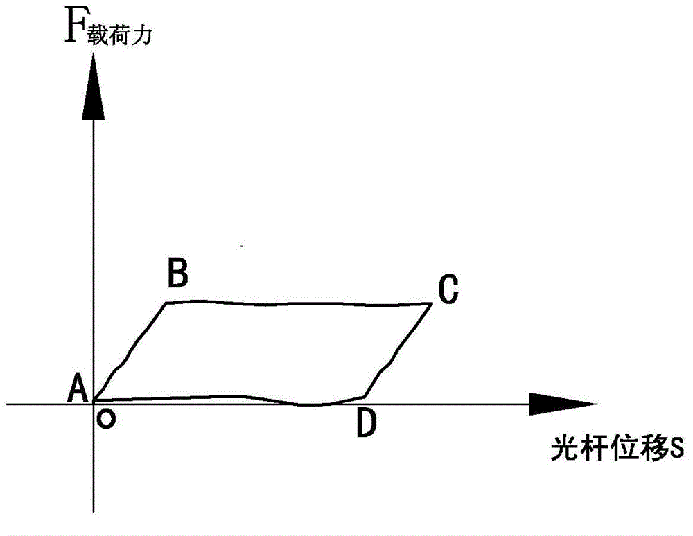
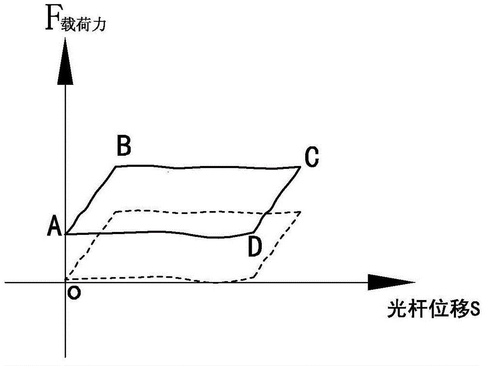
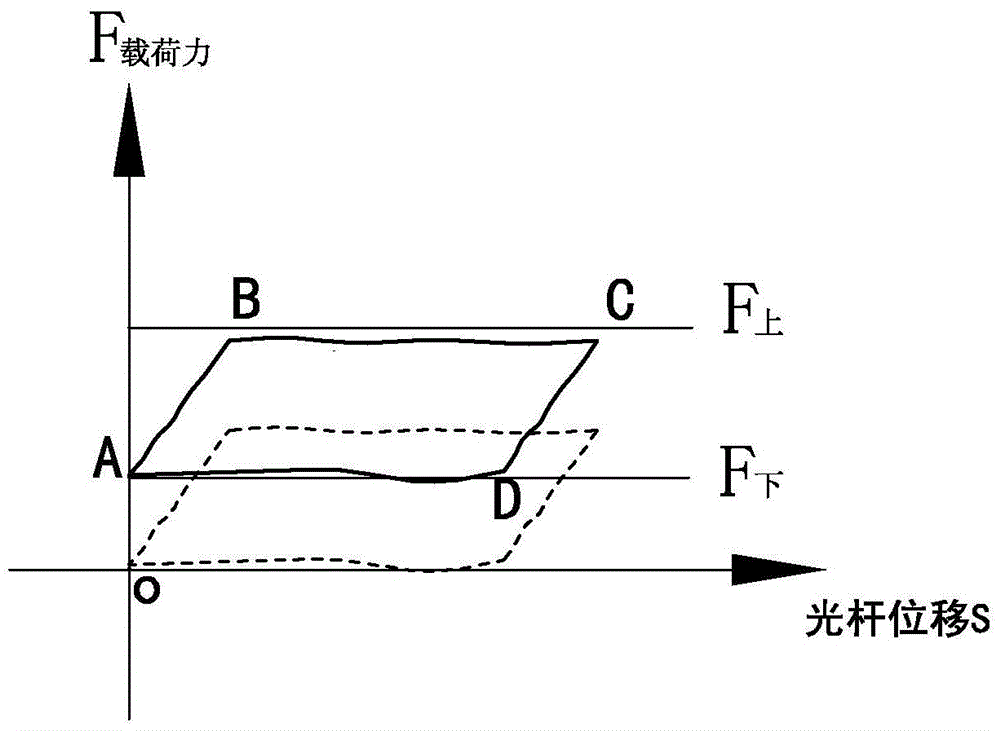
[0029] Specific implementation mode one: as Figure 1~3 As shown, the determination method of the pumping unit well electrical parameters "demonstration diagram" described in the present embodiment is to convert the pumping unit well electrical parameters and the average stroke to the wellhead load force and displacement to determine the "demonstration diagram" (i.e. Determine the "dynamometer diagram" by converting to wellhead load force displacement), the implementation process of the method is:

[0030] Step 1. During the normal working process of the pumping unit, collect the electrical parameters of the pumping well in real time at high speed, measure the electrical parameters of the motor input terminal: current, voltage, active power, and the data acquisition speed is greater than or equal to 20 times per second. The moment when the crank of the oil rig runs to the upper dead point and the lower dead point corresponding to the suspension point of the wellhead of the pum...

specific Embodiment approach 2

[0059] Specific embodiment two: the process of the adjustment method of a kind of pumping well operation balance described in the present embodiment is:

[0060] Step 1. During the normal working process of the pumping unit, collect the electrical parameters of the pumping well in real time at high speed. The data collection speed is greater than or equal to 20 times per second. Simultaneously measure the electrical parameters of the motor input terminal: current, voltage, active power, and determine the pumping unit. The moment when the crank of the pumping unit runs to the upper dead point of the suspension point of the wellhead of the pumping unit and the moment to the lower dead point;

[0061] Pumping unit stroke: the crank balance weight of the pumping unit runs to the bottom dead center of the corresponding pumping unit wellhead (the crank operating angle is 0° or 360°), and the crank balance weight of the pumping unit runs to the top dead center of the corresponding pum...

specific Embodiment approach 3

[0065] This embodiment describes the second specific embodiment in detail. Give an example to illustrate the net torque superposition value P of the up and down strokes for multiple consecutive strokes 上下 The calculation process, assuming that it is required to obtain the net torque superposition value P of up and down strokes for m consecutive strokes 上下 and the torque factor of m strokes

[0066] The net torque data collected on the upstroke of the first stroke is X 1 、X 2 、X 3 ,...X n , then the average value P of all net torques in the upstroke in this stroke 1上 For: (X 1 +X 2 +X 3 +…+X n ) / n;

[0067] The torque factor calculated corresponding to the upstroke of the first stroke and data acquisition is Z 1 ,Z 2 ,Z 3 ,……Z n , then the average value of all torque factors in the upstroke in this stroke For: (Z 1 +Z 2 +Z 3 +…+Z n ) / n;

[0068] The net torque data collected on the downstroke of the first stroke is Y 1 , Y 2 , Y 3 、…Y n , then the ave...


PUM


Abstract

The invention provides a method for determining an indicator diagram of electrical parameters of a rod-pumped well and belongs to the technical field of oil production of oil fields. The method aims at achieving convenient and practical measurement of the indicator diagram of the electrical parameters of the rod-pumped well on site. The method is characterized in that top dead center moments and bottom dead center moments are determined periodically, active powers of electrical parameters of up strokes and down strokes of the rod-pumped well are processed in a decomposition mode, and input end active power of the up strokes and the down strokes is obtained respectively and are calculated and converted into wellhead loading force; adjustment is conducted through balance blocks for operation balance of a pumping unit, actually measured data are used for further correcting the weights of the crank balance blocks of the oil pumping unit or retrieving the weights of the crank balance blocks after adjustment, actually measured active power is converted into wellhead loading force F<upper force i>, wellhead loading force F<lower force i> and superposed wellhead loading force F<upper and lower force i>, the wellhead loading force F<upper force i>, the wellhead loading force F<lower force i> and the superposed wellhead loading force F<upper and lower force i> are calculated, superposed and converted into wellhead loading force, and the indicator diagram of trends of the electrical parameters is determined before and after superposition with the crank balance blocks. According to the method, on-site testing is convenient and practical, and online automatic measurement is achieved.

Description

technical field [0001] The invention relates to a method for determining an electrical parameter "indicator diagram" of a pumping well, relates to the technical field of pumping well measurement in an oil field, and belongs to the technical field of oil production in an oil field. Background technique [0002] The surface dynamometer diagram of the pumping unit simplifies the work done by the change of the suspension point load of the polished rod of the pumping unit into an intuitive and closed geometric figure. It is an intuitive reflection of the suspension point load of the polished rod in the dynamic production process and must be mastered by oilfield development technicians. Analytical method. Through the correct analysis and evaluation of the indicator diagram, it can be diagnosed whether the pumping well is in normal production. Combined with the actual field conditions, the downhole production situation is interpreted and analyzed, and the ground dynamometer chart ...

Claims


Application Information

Patent Timeline
IPC IPC(8): E21B44/00E21B47/00
CPCE21B44/00E21B47/009
Inventor 金凯金奇峰邹文江刘春荣尹志国李德荣王伟
Owner 哈尔滨斯特凯峰电子有限公司
Why Eureka
Try Eureka