Full free-flying wind tunnel test mechanism for sub-cluster separation

A technology of wind tunnel test and submunition, which is applied in the field of aerospace engineering, can solve the problems that the size of the wind tunnel of the ejection mechanism of the model cannot be increased, it is difficult to control the ejection speed and angular velocity of the model, and it is difficult to realize the full free flight test, etc., so as to achieve a compact structure , reliable performance, and the effect of free movement of the organization

Active Publication Date: 2016-03-02
CHINA ACAD OF AEROSPACE AERODYNAMICS
View PDF3 Cites 0 Cited by
  • Summary
  • Abstract
  • Description
  • Claims
  • Application Information

AI Technical Summary

Problems solved by technology

[0004] (1) When the bullet model is ejected with a single spring, the spring action point is near the center of mass of the bullet. This ejection method is not only time-consuming and laborious to install, but also difficult to control the speed and angular velocity of the model ejection. Multiple debugging tests are required before the test.
[0005] (2) When the bullet model is pushed by the four-bar mechanism, because the four-bar mechanism is unstable, and one power point cannot complete the flat throwing action of the model, the mechanism needs two power sources
This makes the model mechanism more complicated, and the model cannot be made small, the model ejection mechanism and the size of the required wind tunnel are increased accordingly, which is in contradiction with the conventional free-flying wind tunnel test, and it is difficult to realize the full-free flight test
[0006] (3) The operation principle of the single push rod release mechanism is simple, but because the entire mechanism rotates around one axis, it often causes the bullet to have a considerable additional angular velocity before it is released from the bin. If it needs to be applied to engineering, the mechanism needs to be improved

Method used


Image

  • Full free-flying wind tunnel test mechanism for sub-cluster separation
  • Full free-flying wind tunnel test mechanism for sub-cluster separation
  • Full free-flying wind tunnel test mechanism for sub-cluster separation

Examples


Embodiment Construction

[0031] The present invention will be further described below in conjunction with the accompanying drawings.

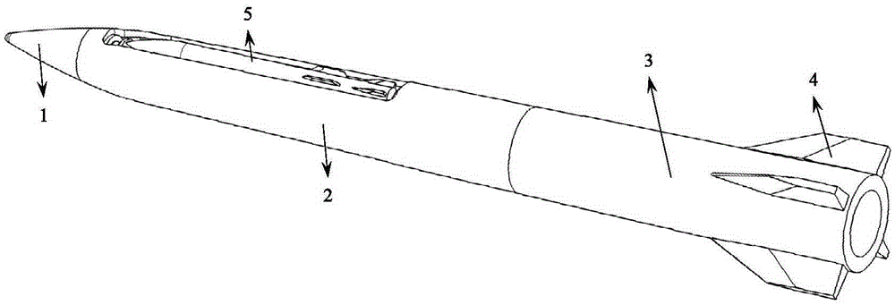
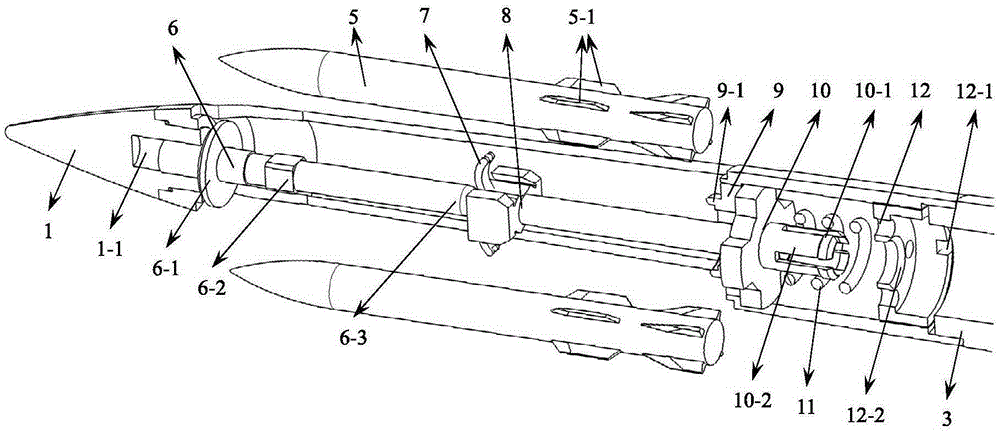
[0032] see Figure 1 to Figure 6As shown, 1 is the head of the female bullet, which has a threaded hole 1-1, and the blocking rod 6 is connected with the threaded hole 1-1 of the female bullet through threads. There is a positioning plate 6-1 on the blocking rod 6, and the positioning plate 6-1 can limit the axial forward movement of the bullet along the parent bullet, and plays the role of positioning; there is a square platform 6-2 on the blocking rod, and the square platform is beneficial to the blocking rod. The 6 installations; the blocking rod curved surface head 6-3 is arranged on the blocking rod 6, and the head of the blocking rod curved surface head 6-3 has many forms, including a spherical head, an elliptical ball head, a parabolic ball head and the like. The bullet head 1 is connected to the middle part 2 of the bullet through threads, and the rear part 3 ...


PUM


Abstract

The invention discloses a cluster munition separation free flight wind tunnel testing mechanism. The cluster munition separation free flight wind tunnel testing mechanism comprises a blocking rod, a transmission mechanism, a positioning block, a spring mechanism and an unlocking mechanism. The blocking rod comprises a positioning plate and a shaft rod, wherein one end of the shaft rod is provided with a positioning plate and arranged in the axis position at the rear end of a primary munition head part, and a curved surface head is arranged at the other end of the shaft rod. After a thrust mechanism is installed behind the blocking rod. The transmission mechanism comprises two or more small push rods and large push rods, wherein the small push rods are arranged on the head portions of the large push rods respectively, the rear ends of the large push rods penetrate through the positioning block to be connected with the spring mechanism, the large push rods and the large push rods are coaxial, grooves used for positioning and clamping bullets are formed in the large push rods, the positioning block is arranged on the primary munition, the spring mechanism is arranged on the rear portion of a primary munition middle section, the unlocking mechanism is connected with a transmitting mechanism, and the unlocking mechanism is assembled on the spring mechanism. The whole cluster munition separation free flight wind tunnel testing mechanism has the advantages of being reliable in performance, rapid in reaction, reasonable in design, convenient to machine and install, compact in structure, high in space utilization rate and the like.

Description

Technical field: [0001] The invention relates to the support and launch of a wind tunnel test model, in particular to a fully free-flying wind tunnel test mechanism for separation of submunitions and bombs, and belongs to the field of aerospace engineering. technical background: [0002] Submunitions have the advantages of large killing range and high damage efficiency. They are widely used in anti-cluster targets and are the preferred weapons and equipment for regional wars. The lethality of submunitions largely depends on the dispensing effect of bullets. How to effectively distribute bullets so that they can reach the preset distribution position is an important link in the development of submunitions. Therefore, it is necessary to carry out preliminary free flight test research. Since the free flight test models are generally small, and most of the parent bombs are relatively slender, and there are bullets in the slender parent bombs, the space left for the ejection me...

Claims


Application Information

Patent Timeline
Patent Type & Authority Patents(China)
IPC IPC(8): F42B35/00
Inventor 薛飞杨益农
Owner CHINA ACAD OF AEROSPACE AERODYNAMICS
Why Eureka
Try Eureka