Optimization method of relative orbit transfer path of spacecraft based on time-fuel optimum control

An optimal control and relative orbit technology, applied in attitude control and other directions, can solve problems such as not considering the limited thrust amplitude and only considering time

Active Publication Date: 2015-04-22
HARBIN INST OF TECH
View PDF7 Cites 23 Cited by
  • Summary
  • Abstract
  • Description
  • Claims
  • Application Information

AI Technical Summary

Problems solved by technology

[0004] In order to solve the problem of tracking the spacecraft in the relative orbital coordinate system, the existing method does not consider

Method used


Image

  • Optimization method of relative orbit transfer path of spacecraft based on time-fuel optimum control
  • Optimization method of relative orbit transfer path of spacecraft based on time-fuel optimum control
  • Optimization method of relative orbit transfer path of spacecraft based on time-fuel optimum control

Examples


specific Embodiment approach 1

[0069] Specific embodiment one: based on time-fuel optimal control, the relative orbit transfer trajectory optimization method of the spacecraft comprises the following steps:

[0070] Step 1. Establish relative orbital motion dynamics model:

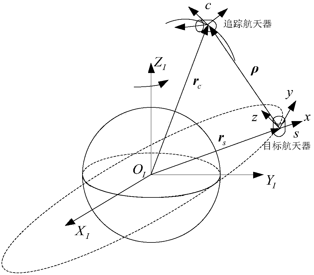
[0071] In the geocentric inertial coordinate system O-X I Y I Z I Among them, record the target spacecraft as s, and the tracking spacecraft as c; suppose the target spacecraft s is in a near-circular orbit, take the orbital coordinate system s-xyz of the target spacecraft as the relative motion coordinate system, and the tracking spacecraft as c The position where the target spacecraft is s is the relative position, and the coordinates of the relative position are established on the orbital coordinate system s-xyz; the orbital coordinate system s-xyz and the earth-centered inertial coordinate system O-X I Y I Z I relationship such as figure 1 shown;

[0072] Without considering the perturbation, the dynamic equations of the targ...

Embodiment

[0154] Taking the optimal transfer from 50km to 10km as an example, take [x 0 ,y 0 ,z 0 ] = [24000, 40000, 18000] m, [x f ,y f ,z f ]=[4800, 8000, 3600]m, the final state error is required to be less than 200m, and the control acceleration amplitude generated by the continuous thrust in each coordinate axis direction should not exceed 0.01m / s 2 .

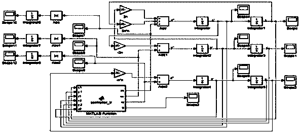
[0155] Based on the relative motion dynamics model, build a simulation model in Simulink, such as Figure 4 As shown, the control quantity u in the direction of the three coordinate axes x , u y , u z According to the control laws shown in formula (16), they are designed respectively. The values ​​of ρ are respectively selected as 0.015, 0.02, and 0.024 to represent the three situations of partial fuel, compromise, and partial time for simulation.

[0156] Taking ρ=0.015 as an example, the position of the three-axis direction changes with time as shown in Figure 5 As shown, the spatial trajectory of the orbital transfer ...


PUM


Abstract

The invention provides an optimization method of a relative orbit transfer path of a spacecraft based on time-fuel optimum control and relates to the optimization method of the relative orbit transfer path of the spacecraft. The optimization method of the relative orbit transfer path of the spacecraft is used for solving the problem that the finite thrust amplitude is not considered in the existing method and the problem that only time optimum or only the fuel consumption is considered in the existing method when a tracking spacecraft is in a relative orbit coordinate system. The optimization method comprises the following steps: firstly, establishing a kinematics and dynamics model as shown in the specification of the relative orbit, and designing control quantities ux, uy and uz applied along three axes respectively; secondly, decoupling the kinematics and dynamics model of the relative orbit into three subsystems; after decoupling into three subsystems, transforming the total performance index as shown in the specification considering transfer time and fuel consumption of the tracking spacecraft into monoaxial performance index as shown in the specification of each axis, and finally obtaining the time-fuel optimal control law as shown in the specification for controlling the tracking spacecraft. The optimization method is suitable for optimizing the relative orbit transfer path of the spacecraft.

Description

technical field [0001] The invention relates to a method for optimizing a relative orbital transfer trajectory of a spacecraft. Background technique [0002] The relative orbital motion of spacecraft is to study the law of continuous motion of one spacecraft (tracking spacecraft) around another spacecraft (target spacecraft). The research focus of orbit transfer is mainly in two aspects. On the one hand, it is to consider whether the program can correctly guide the spacecraft to reach the designated position; For the problem of optimal time, starting from engineering reality, the fuel carried by the spacecraft is limited, so sometimes it is necessary to consider the problem of optimal fuel consumption, or even consider the problem of comprehensive optimization of time and fuel consumption. The basic method commonly used to solve the optimal control problem is the classical variational method. When there are constraints on the control quantity, such as the thrust amplitude t...

Claims


Application Information

Patent Timeline
IPC IPC(8): G05D1/08
Inventor 凌惠祥孙延超龚有敏李传江马广富董经纬
Owner HARBIN INST OF TECH
Why Eureka
Try Eureka