Shift register as well as driving method thereof, gate driving circuit and display device

A shift register and gate connection technology is applied in the fields of display devices, shift registers and driving methods thereof, and gate drive circuits, and can solve the problems of output signal deterioration, affecting output signals, affecting the output effect of shift registers, etc.

Active Publication Date: 2015-04-22
BOE TECH GRP CO LTD
View PDF5 Cites 40 Cited by
  • Summary
  • Abstract
  • Description
  • Claims
  • Application Information

AI Technical Summary

Problems solved by technology

[0004] The inventors found that when the second clock signal input by the second clock signal input terminal CK2 changes, the signal on the gate of M2 will be affected by the coupling capacitance formed...

Method used


Image

  • Shift register as well as driving method thereof, gate driving circuit and display device
  • Shift register as well as driving method thereof, gate driving circuit and display device
  • Shift register as well as driving method thereof, gate driving circuit and display device

Examples


Embodiment 1

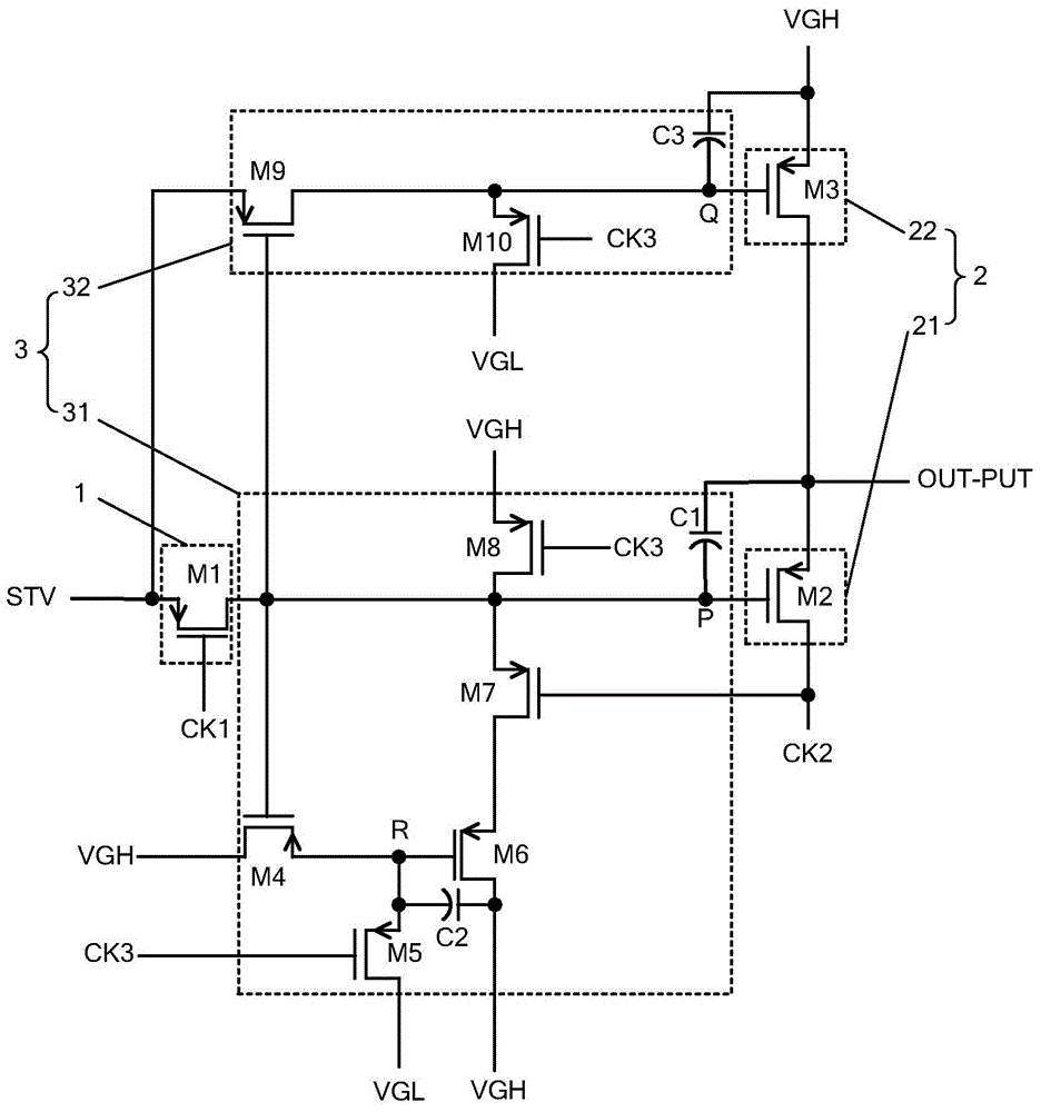
[0111] An embodiment of the present invention provides a shift register, such as image 3 with Figure 4 As shown, the shift register includes an input module 1 , an output module 2 and an output control module 3 .

[0112] Specifically, the input module 1 controls the signal transmission between the start signal input terminal STV and the first node P.

[0113] The output module 2 controls the signal output of the signal output terminal OUTPUT, and the output module 2 includes a first output unit 21 and a second output unit 22, wherein the first output unit 21 is connected to the first node P, and the first node P controls the first output unit 21. The first output unit 21 controls the signal transmission between the second clock signal input terminal CK2 and the signal output terminal OUTPUT, the second output unit 22 is connected to the second node Q, and the second node Q controls the second output unit 22, and the second The output unit 22 controls the signal transmissi...

Embodiment 2

[0147] An embodiment of the present invention provides a driving method for the shift register described in Embodiment 1, and the driving method for the shift register includes:

[0148] The signal transmission between the start signal input terminal STV and the first node P is controlled by the input module 1 .

[0149] The signal output of the signal output terminal OUTPUT is controlled by the output module 2 .

[0150] The output module 2 is controlled by the output control module 3 .

[0151] Wherein, the output control module 3 includes a first control unit 31 and a second control unit 32, and the output module 2 includes a first output unit 21 and a second output unit 22, wherein the first control unit 31 controls the power of the first node P Level, the first node P controls the first output unit 21, the level of the second node Q is controlled by the second control unit 32, and the second node Q controls the second output unit 22, so that the first node P and the seco...


PUM


Abstract

The embodiment of the invention discloses a shift register as well as a driving method of the shift register, a gate driving circuit and a display device, and relates to the technical field of display. The influence on an output signal by the change of a clock signal associated with an output module can be reduced, and an output effect of the shift register is improved. The shift register comprises an input module, an output module and an output control module, wherein the output module comprises a first output unit and a second output unit; a first node is used for controlling the first output unit; the first output unit is used for controlling signal transmission between a signal input end and a signal output end of a second clock signal; a second node is used for controlling the second output unit, and the second output unit is used for controlling signal transmission between a signal input end and a signal output end of a high level; the output control module comprises a first control unit and a second control unit, wherein the first control unit is used for controlling the level of the first node, and the second control unit is used for controlling the level of the second node.

Description

technical field [0001] The present invention relates to the field of display technology, in particular to a shift register, a driving method thereof, a gate driving circuit, and a display device. Background technique [0002] In order to realize normal display of the display device, the display device needs to include a gate driving circuit. Specifically, the gate driving circuit includes a plurality of shift registers cascaded with each other. [0003] Specifically, the structure of the shift register is as figure 1 As shown, the shift register includes an input module, an output module and an output control module, wherein the input module includes M1, the output module includes M2 and M3, and the output control module includes M4, M5, C1 and C2, wherein M1-M5 are all PMOSFET turned on for low level. The timing diagram of its working process is as follows: figure 2 As shown, in the t1 stage, the start signal input by the start signal input terminal STV and the first c...

Claims


Application Information

Patent Timeline
IPC IPC(8): G09G3/20G09G3/36G11C19/28
CPCG09G3/20G09G3/36G09G2310/0286G11C19/28
Inventor 马占洁孙拓
Owner BOE TECH GRP CO LTD
Why Eureka
Try Eureka