
Micro-strip elliptic function band rejection filter

A band-stop filter and elliptic function technology, applied in waveguide-type devices, resonators, electrical components, etc., can solve the problems of low square coefficient, small notch depth, and complex prototype circuits, and achieve small passband insertion loss, The effect of deep notch suppression and high squareness factor

Active Publication Date: 2015-04-22
CHINA ELECTRONICS TECH GROUP CORP NO 16 INST
View PDF5 Cites 2 Cited by
  • Summary
  • Abstract
  • Description
  • Claims
  • Application Information

AI Technical Summary

Problems solved by technology

However, due to the complexity of the prototype circuit of the elliptic function filter, the corresponding microwave filter is used in many forms of transmission lines such as striplines and waveguides, but not many forms are applied to microstrip lines.
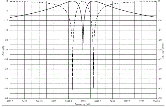
The conventional design method is based on the Chebyshev function, and there is no precise theoretical formula for calculation. The designed filter can only realize the pseudo / quasi-elliptic function transmission curve. Under the same filter order, there are small notch depth, low square coefficient, pass Insufficient with large insertion loss

Method used


Image

  • Micro-strip elliptic function band rejection filter
  • Micro-strip elliptic function band rejection filter
  • Micro-strip elliptic function band rejection filter

Examples


Embodiment Construction

[0017] The present invention will be further described below in conjunction with accompanying drawing:

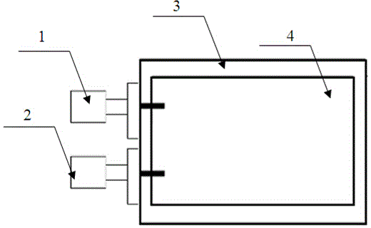
[0018] Such as figure 1 A microstrip elliptic function band-stop filter shown includes an input SMA connector 1 , an output SMA connector 2 , a box body 3 and a microstrip elliptic function band-stop filter circuit 4 . The microstrip elliptic function band-stop filter circuit 4 is arranged inside the box body 3, and the microstrip elliptic function band-stop filter circuit 4 is welded to the bottom of the box body 3 through a 0.1 mm thick indium sheet, and its input and output The terminals are welded to the input SMA connector 1 and the output SMA connector 2 respectively.

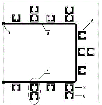
[0019] Specifically, as figure 2 As shown, the microstrip elliptic function band-stop filter circuit 4 includes input and output pads 5 , a microstrip main line 6 , and single-mode resonators 9 and dual-mode resonators 7 arranged at intervals along the microstrip main line 6 . The single-mode reson...


PUM


Abstract

The invention relates to a micro-strip elliptic function band rejection filter which comprises an input SWA connector, an output SWA connector and a micro-strip elliptic function band rejection filter circuit. The micro-strip elliptic function band rejection filter circuit comprises a micro-strip main line, single-mode resonators and double-mode resonators, wherein the single-mode resonators and the double-mode resonators are arranged along the micro-strip main line at intervals. The single-mode resonators and the double-mode resonators are connected with the micro-strip main line in a coupled mode. The center frequency of the single-mode resonators is the same as that of the double-mode resonators, the interval, between the single-mode resonators and the double-mode resonators, of the micro-strip main line is 1 / 4 wavelength. The double-mode resonators are each composed of two resonance units which are coupled to each other, wherein both the two resonance units are single-mode resonators of 1 / 2 wavelength, and the resonance frequency of the two resonance units are located at the two sides of the center frequency respectively. By means of the technical scheme, the micro-strip elliptic function band rejection filter has the elliptic function transmission feature and has the advantages of being deep in notch suppression, high in rectangle coefficient, low in passband insertion loss and the like.

Description

technical field [0001] The invention relates to the technical field of microwave devices, in particular to a microstrip elliptic function band-stop filter. Background technique [0002] Compared with the Chebyshev function filter and the Butterworth function filter, the elliptic function filter of the same order can achieve a steeper cutoff. However, due to the complexity of the prototype circuit of the elliptic function filter, the corresponding microwave filter is used in many forms of transmission lines such as striplines and waveguides, but not many forms are used in microstrip lines. The conventional design method is based on the Chebyshev function, and there is no precise calculation theoretical formula. The designed filter can only realize the pseudo / quasi-elliptic function transmission curve. Under the same filter order, there are small notch depth, low square coefficient, pass The belt has a large insertion loss and other deficiencies. Contents of the inventi...

Claims


Application Information

Patent Timeline
Patent Type & Authority Applications(China)
IPC IPC(8): H01P1/203H01P7/00
Inventor 刘洋左涛王生旺张士刚陆勤龙杨时红宾峰陈新民肖南孙文娟阮晓明高文斌
Owner CHINA ELECTRONICS TECH GROUP CORP NO 16 INST
Learn More