Reactive compensation method and device having transformer reactive current real-time compensation function

A real-time compensation and compensation device technology, applied in the direction of reactive power adjustment/elimination/compensation, circuit devices, electrical components, etc., can solve the problems of no transformer reactive power compensation, user power factor can not meet the standard, etc., to reduce switching times, achieve rapidity and non-polarity, and solve the effect of low power factor

Active Publication Date: 2015-04-22
XIAN ACTIONPOWER ELECTRIC
View PDF4 Cites 13 Cited by
  • Summary
  • Abstract
  • Description
  • Claims
  • Application Information

AI Technical Summary

Problems solved by technology

[0008] In order to solve the technical problem that the existing compensation device does not compensate the reactive power of the transformer, which leads to the failure of the user's power factor to reach

Method used


Image

  • Reactive compensation method and device having transformer reactive current real-time compensation function
  • Reactive compensation method and device having transformer reactive current real-time compensation function
  • Reactive compensation method and device having transformer reactive current real-time compensation function

Examples


Embodiment Construction

[0047] Starting from the principle of the present invention, the present invention will be described in detail in conjunction with the accompanying drawings.

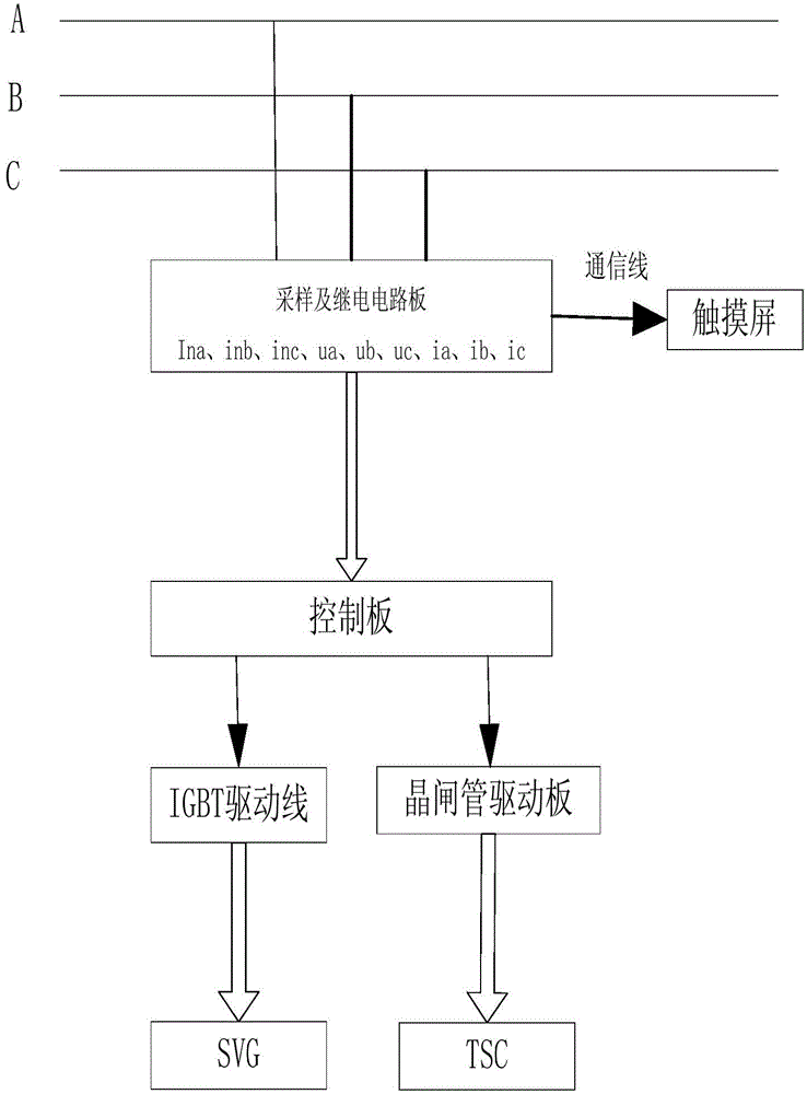
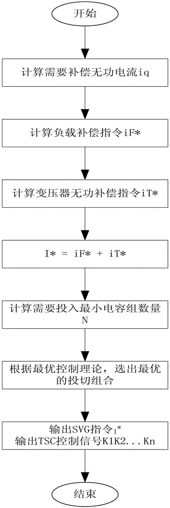
[0048] The present invention realizes the optimization of the mixed control of SVG and TSC by detecting the instantaneous value of grid-side current in real time, and at the same time compensates the reactive power loss of the transformer in real time, which is embodied in the following two aspects:

[0049] 1. Optimal control

[0050] According to the size of the detected reactive power on the grid side, determine the number of capacitor banks to be put into operation, and then use the switching strategy as a limiting condition, and obtain the only switching combination with the least input according to the optimal control theory, and control N branches capacitor bank (the N branch capacitor bank can be equal-capacity capacitor bank or unequal-capacity capacitor bank), and the optimal selection of the cooperation proce...


PUM


Abstract

The invention discloses a reactive compensation method and device having a transformer reactive current real-time compensation function and belongs to the field of electric energy quality control. The reactive compensation method and device are used for conducting real-time calculation on the no-load loss and the loss (changing along with the load rate) in the load-available condition, real-time compensation of reactive current of a transformer is achieved, and the problem that the power factor is low due to the reactive loss of the transformer is solved. Meanwhile, the optimal control theory is used for calculating the switching strategy of capacitance compensation of an SVG and a TSC, switching of the SVG and the TSC can reach the optimized effect, and the advantages of fastness and nonpolarity are achieved completely.

Description

technical field [0001] The invention relates to an intelligent dynamic reactive power compensation device, which belongs to the field of power quality control. Background technique [0002] With the development of the power system, the demand for fast and dynamic compensation of reactive power is also increasing. Therefore, fast response, continuous adjustment, simple operation, and low cost have become new requirements for reactive power compensation. [0003] The early reactive power dynamic compensation device was a synchronous condenser, but because it was a rotating motor, it had large losses and noise, complex operation and maintenance, and slow response speed, so it was gradually replaced by a static reactive power compensation device (SVC). [0004] Although SVC has the advantages of fast response, simple maintenance, and high reliability, it also has the disadvantages of large equipment, easy to generate harmonics, easy to generate resonance, and cannot be continuou...

Claims


Application Information

Patent Timeline
IPC IPC(8): H02J3/18
CPCH02J3/18H02J3/1878Y02E40/10
Inventor 王森张丽娟高鹏
Owner XIAN ACTIONPOWER ELECTRIC
Why Eureka
Try Eureka