
Small-sized underwater low-frequency acoustic transmitter

A transmitter and small water technology, applied in the direction of electrical components, transmission systems, etc., can solve the problems of accidental interference in the test process, pollution of useful sound signals, large volume, and heavy weight, etc., to achieve simple and convenient debugging, improve noise signal strength, The effect of a small number of components

Inactive Publication Date: 2015-04-22
710TH RES INST OF CHINA SHIPBUILDING IND CORP
View PDF2 Cites 5 Cited by
  • Summary
  • Abstract
  • Description
  • Claims
  • Application Information

AI Technical Summary

Problems solved by technology

[0002] In underwater acoustics research, low-frequency sound sources are commonly used underwater equipment, and the conventional underwater acoustic signal transmission system composed of standard general-purpose underwater acoustic equipment such as signal generators, power amplifiers, and low-frequency transducers is not only relatively small in size and weight This kind of general-purpose equipment needs external AC power supply, so when testing in wild waters, the power generation equipment is often required to provide an external power supply, and the vibration and radiation noise of the power generation equipment spread underwater, and the It will pollute the useful acoustic signal emitted by the sound source of the underwater test, and bring unexpected interference to the test process

Method used


Image

  • Small-sized underwater low-frequency acoustic transmitter
  • Small-sized underwater low-frequency acoustic transmitter
  • Small-sized underwater low-frequency acoustic transmitter

Examples


Embodiment Construction

[0029] The present invention will be described in detail below with reference to the accompanying drawings and examples.

[0030] This embodiment provides a small underwater low frequency acoustic transmitter, its system block diagram is as follows figure 1 As shown, the transmitter includes a signal generating circuit, a power amplifier circuit, a magnetoelectric flexural transducer and a battery pack.

[0031] signal generating circuit

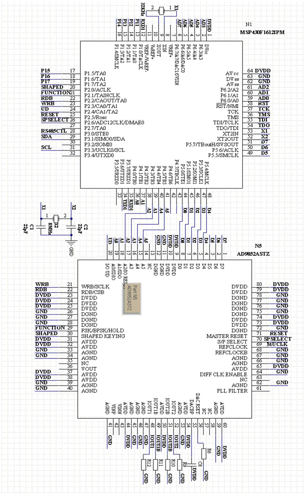
[0032] The signal generating circuit includes two parts: a band-limited noise signal generator circuit and a digital signal generator circuit.

[0033] 1), band-limited noise signal generator circuit

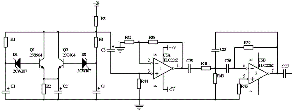
[0034] The band-limited noise signal generator circuit uses the Zener diode to generate a broadband AC noise signal when it reaches the Zener voltage and works in an avalanche state. The broadband AC noise signal is amplified and band-pass filtered to form a band-limited noise signal. In this example, if figure 2 Shown is the band-limited...


PUM


Abstract

The invention discloses an underwater low-frequency acoustic transmitter, and belongs to the technical field of hydroacoustic survey. The transmitter comprises a signal generating circuit, a power amplifying circuit, a magneto-electric flextensional transducer and a battery pack, wherein the signal generating circuit comprises a band-limited noise signal generator circuit for generating a band limited noise signal and a digital signal generator circuit for generating a sinusoidal single-frequency signal, a frequency-modulated signal and a sweeping frequency signal; the power amplifying circuit comprises two integrated power operational amplifiers constructing a non-inverting amplifier and an inverting amplifier respectively which are connected to the positive / negative input ends of the magneto-electric flextensional transducer; the battery pack is used for supplying power to the signal generating circuit and the power amplifying circuit. The signal generating circuit is used for generating a low-frequency sinusoidal signal, the frequency-modulated signal, the sweeping frequency signal or the band-limited noise signal. After the signals are amplified by the power amplifying circuit, the magneto-electric flextensional transducer is driven to transform electric energy into mechanical energy, and the mechanical energy is emitted in the form of sound waves.

Description

technical field [0001] The invention relates to a device for transmitting underwater low-frequency acoustic signals, and belongs to the technical field of underwater acoustics research. Background technique [0002] In underwater acoustics research, low-frequency sound sources are commonly used underwater equipment, and the conventional underwater acoustic signal transmission system composed of standard general-purpose underwater acoustic equipment such as signal generators, power amplifiers, and low-frequency transducers is not only relatively small in size and weight This kind of general-purpose equipment needs external AC power supply, so when testing in wild waters, the power generation equipment is often required to provide an external power supply, and the vibration and radiation noise of the power generation equipment spread underwater, and the It will pollute the useful acoustic signal emitted by the underwater test sound source and bring unexpected interference to t...

Claims


Application Information

Patent Timeline
Patent Type & Authority Applications(China)
IPC IPC(8): H04B1/04H04B13/02
Inventor 付继伟高伟满令斌汪小亚刘晓东
Owner 710TH RES INST OF CHINA SHIPBUILDING IND CORP
Learn More