Eureka AIR delivers breakthrough ideas for toughest innovation challenges, trusted by R&D personnel around the world.

Vacuum degassing tank

A vacuum degassing and tank technology, which is applied in the direction of liquid degassing, chemical instruments and methods, separation methods, etc., can solve the problems of affecting the degassing effect of degassing tanks, affecting the working quality of vacuum pumps, and wasting heat energy, etc., to improve the market Competitiveness, prolonging the service life of equipment, and improving degassing effect

Active Publication Date: 2015-04-29
东莞埃欧热能技术有限公司
View PDF5 Cites 0 Cited by
  • Summary
  • Abstract
  • Description
  • Claims
  • Application Information

AI Technical Summary

Problems solved by technology

[0004] There are some deficiencies in the above-mentioned degassing tank. Because the oxygen (air) and aromatic gas contained in the feed liquid are only blocked by the filter screen after volatilization, they are directly sucked away by the vacuum pump. At this time, the moisture in the oxygen (air) and aromatic gas It will also be sucked away by the vacuum pump, which will cause waste and affect the working quality of the vacuum pump. In addition, the temperature of oxygen (air) and aromatic gas is still relatively high, so they are directly pumped away, resulting in a waste of heat energy and affecting the degassing process. The degassing effect of the gas tank

Method used


Image

  • Vacuum degassing tank
  • Vacuum degassing tank
  • Vacuum degassing tank

Examples


Embodiment Construction

[0025] The present invention will be further described below in conjunction with specific embodiments and accompanying drawings.

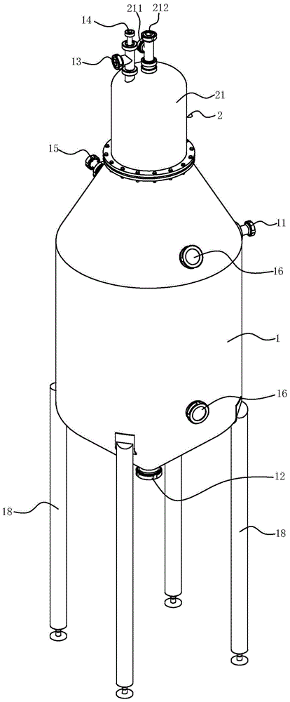
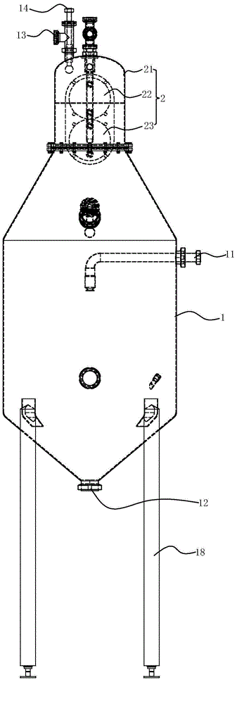
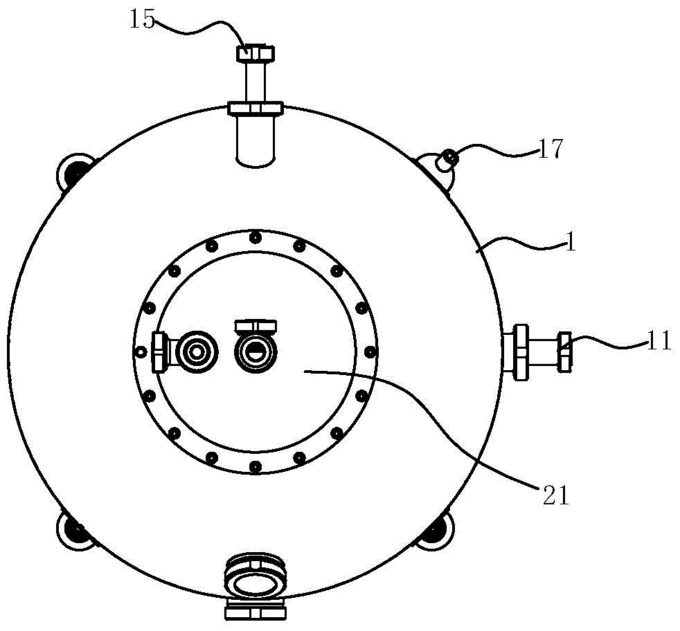
[0026] See Figure 1-5 Shown is a vacuum degassing tank, which includes a tank body 1 , a feed liquid inlet 11 and a feed liquid outlet 12 arranged on the tank body 1 , and a detachable condenser assembly 2 .

[0027] The condenser assembly 2 is arranged on the upper part of the tank body 1. After boiling, the feed liquid evaporates and rises to the top of the tank body 1, and enters the condenser assembly 2 for condensation in time, which can reduce loss.

[0028] The upper end of the tank 1 is provided with a flange, and the condenser assembly 2 is installed at the flange. The condenser assembly 2 includes: a housing 21 installed on the upper end of the tank 1 and a housing 21 The first heat exchange core 22 and the second heat exchange core 23 are connected in parallel with each other.

[0029] The shell 21 and the upper end of the tank body 1...


PUM


Abstract

The invention discloses a vacuum degassing tank. The vacuum degassing tank comprises a tank body, and a feed liquid inlet and a feed liquid outlet which are formed in the tank body, wherein a flange is arranged at the upper end of the tank body; a demountable condenser assembly is mounted on the flange; the condenser assembly comprises a shell mounted at the upper end of the tank body, and a first heat exchange core and a second heat exchange core which are mounted in the shell and are connected with each other in parallel; a first plate side channel and a second shell side channel which are isolated with each other are arranged in the first heat exchange core; a second plate side channel and a second shell side channel which are isolated with each other are arranged in the second heat exchange core; the first plate side channel is communicated with the second plate side channel; the first shell side channel is communicated with an inner cavity of the shell and the second shell side channel; the lower end of the second heat exchange stretches into an inner cavity of the tank body, so that the second shell side channel is communicated with the inner cavity of the tank body; a vacuumizing hole communicated with the first shell side channel is formed in the shell. The vacuum degassing tank has an excellent degassing effect and an excellent heat exchange effect, is simple and convenient to use and convenient to repair and maintain, and has high market competitiveness.

Description

Technical field: [0001] The invention relates to the technical field of degassing tank products, in particular to a vacuum degassing tank. Background technique: [0002] The vacuum degassing tank is a device that uses vacuum suction to remove the non-condensable gas contained in the feed liquid. It is an indispensable equipment for the degassing of a series of feed liquids such as dairy products and juices. The function of the vacuum degassing tank is to: remove the air (oxygen) in the feed liquid, inhibit the oxidation of browning, pigments, vitamins, aroma components and other substances, and prevent the quality from deteriorating; remove the suspended particulate gas attached to the feed liquid, inhibit Particles float up to maintain a good appearance; prevent foaming during canning and high-temperature sterilization from affecting sterilization; reduce corrosion to the inner wall of the container. [0003] At present, the working principle of most of the degassing tanks...

Claims


Application Information

Patent Timeline
IPC IPC(8): B01D19/00
Inventor 黄晓东史文忠邓健挺
Owner 东莞埃欧热能技术有限公司
Why Eureka
Eureka Blog
Learn More