
Coating machine and method for detecting and removing dust particles thereof

A coating machine and dust particle technology, which is applied to the device, coating, measuring device and other directions for coating liquid on the surface, which can solve the waste of production raw materials, the inability to accurately determine the specific location of dust particles, and reduce the production line utilization rate, etc. problems, to achieve the effect of ensuring the utilization rate, saving production materials, and reducing costs

Inactive Publication Date: 2017-09-01
BOE TECH GRP CO LTD +1
View PDF4 Cites 0 Cited by
  • Summary
  • Abstract
  • Description
  • Claims
  • Application Information

AI Technical Summary

Problems solved by technology

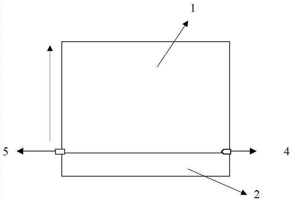
[0003] When coating, the laser is emitted from the laser transmitter 4 and received by the laser receiver 5. Once it encounters a large enough dust particle on the substrate, the laser will be blocked by the dust particle and cannot enter the laser receiver 5. At this time, the coating The machine will alarm, and the dust particle coordinates reported only include the coordinates along the coating direction, and the specific position of the dust particles cannot be accurately determined.
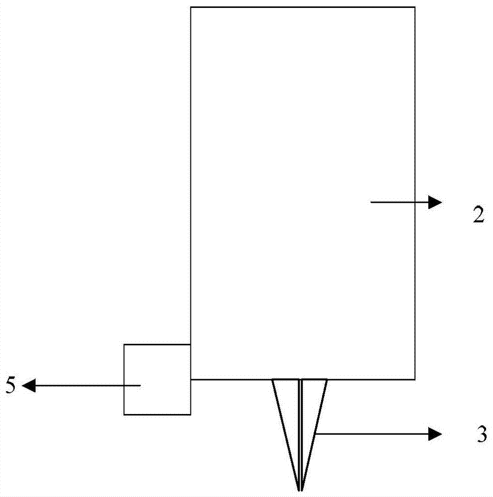
In addition, because the foreign object detection device, namely: the laser transmitter 4 and the laser receiver 5 need to move synchronously with the gantry 2, once dust particles are detected, the nozzle 3 stops coating, and the substrate needs to be separated and regenerated, that is The parts that have been coated before have to be thoroughly cleaned and then re-coated, thus resulting in waste of production materials and reducing the utilization rate of the production line

Method used


Image

  • Coating machine and method for detecting and removing dust particles thereof
  • Coating machine and method for detecting and removing dust particles thereof
  • Coating machine and method for detecting and removing dust particles thereof

Examples


Embodiment Construction

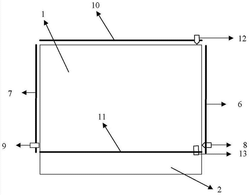
[0037] The basic idea of ​​the embodiment of the present invention is: a group of detection devices are respectively installed in the coating direction and the vertical coating direction, and the purpose of accurately detecting the specific position of dust particles is achieved through the combined use of the two groups of detection devices; The advanced cleaning device achieves the purpose of removing dust particles at one time without causing secondary pollution.

[0038] The present invention will be described in further detail below in conjunction with the accompanying drawings and specific embodiments.

[0039] image 3 It is the top view of the coating machine described in the embodiment of the present invention, as image 3 As shown, on the machine platform, a guide rail parallel to the moving direction of the gantry is provided on the left and right sides of the gantry, namely: the first transmitter guide rail 6 and the first receiver guide rail 7, The first transmi...


PUM


Abstract

The invention discloses a coating machine, comprising: a machine platform, a gantry, and a nozzle arranged directly under the gantry; The guide rails are parallel to the direction of movement, one guide rail is loaded with the first light emitter, and the other guide rail is loaded with the first light receiver; Guide rails perpendicular to the movement direction of the gantry, one guide rail is loaded with a second light emitter, and the other guide rail is loaded with a second light receiver; wherein, the first light receiver is used to receive the light emitted by the first light emitter ; The second light emitter is used to receive the light emitted by the second light emitter. The invention also discloses a method for detecting and removing dust particles by using the coating machine. The technical solution provided by the application can accurately determine the position of the dust particles on the surface of the substrate, and can quickly and completely remove the dust particles, reducing costs .

Description

technical field [0001] The invention relates to a coating process, in particular to a coating machine and a method for detecting and removing dust particles thereof. Background technique [0002] Since dust particles can adversely affect the coating effect of the substrate, it is necessary to detect dust particles. The foreign matter detection of the existing coating machine is realized through the laser transmitter and the laser receiver respectively arranged on both sides of the front bottom of the Gantry, such as figure 1 shown. Below the structure of existing coating machine is briefly described, as figure 1 , 2 As shown, the coating machine includes: a machine platform 1 for carrying a substrate, a gantry 2 for coating the substrate, and directly below the gantry 2 is a nozzle 3, that is, the outlet of the coating liquid, and the outlet of the nozzle 3 A slit is formed, the length of which is basically the same as the width of the substrate. The front side of the ga...

Claims


Application Information

Patent Timeline
Patent Type & Authority Patents(China)
IPC IPC(8): B05D3/00B05D3/12G01B11/00
Inventor 郭杨辰方群
Owner BOE TECH GRP CO LTD
Learn More