Supercharge Your Innovation With Domain-Expert AI Agents!

Pneumatic bending machine for reverser

A commutator and bending machine technology, applied in the field of commutators, can solve the problems of poor forming quality of commutators, delay in processing time, low processing efficiency, etc., and achieve small use environment restrictions, sufficient time utilization, and high forming efficiency Improved effect

Active Publication Date: 2015-04-29
HUARUI ELECTRICAL APPLIANCE
View PDF10 Cites 0 Cited by
  • Summary
  • Abstract
  • Description
  • Claims
  • Application Information

AI Technical Summary

Problems solved by technology

[0003] The traditional commutator hook is generally composed of multiple processes, and each process needs to be equipped with corresponding equipment, and each set of equipment is operated by a corresponding operator, which leads to low processing efficiency and high processing cost. Therefore, people invented A forming device specially used to form commutator hooks
[0004] For example, the utility model whose authorized announcement number is CN 201760484 U discloses a coiled plate type commutator copper sleeve outer hook forming device, including a chassis, a workbench is provided on the chassis, and the workbench is provided with intermittently rotating On the turntable, there is a circle of workpiece forming seats evenly distributed on the turntable. A bracket is placed on the turntable, and the bracket is fixed on the workbench. On the bracket, at least two groups of forming rods are progressively formed along the movement track direction of the workpiece forming seat. , the forming rod is provided with an up and down drive device, although this forming device adopts a turntable forming method, which improves the processing efficiency, but also has the following technical problems at the same time, 1. Due to the use of a turntable forming method, the entire forming device The volume is larger, the floor area is larger, and the structure is relatively loose. Generally, a large factory building is required to meet the production needs of the molding device, and the use of the environment is relatively restricted, which makes the production cost higher; 2. In addition, the molding device. The overall structure is relatively complicated. Although the turntable processing method is convenient, when it breaks down, the entire forming device will stop working, which delays the processing time and is not easy to maintain; 3. The commutator needs a relatively stable environment during forming. In order to ensure that it has better precision, and the forming device adopts a turntable forming method, the turntable is less stable during the rotation process, and it is easy to shake, resulting in low forming precision of the commutator and poor forming quality of the commutator. poor

Method used


Image

  • Pneumatic bending machine for reverser
  • Pneumatic bending machine for reverser
  • Pneumatic bending machine for reverser

Examples


Embodiment Construction

[0029] The following are specific embodiments of the present invention and in conjunction with the accompanying drawings, the technical solutions of the present invention are further described, but the present invention is not limited to these embodiments.

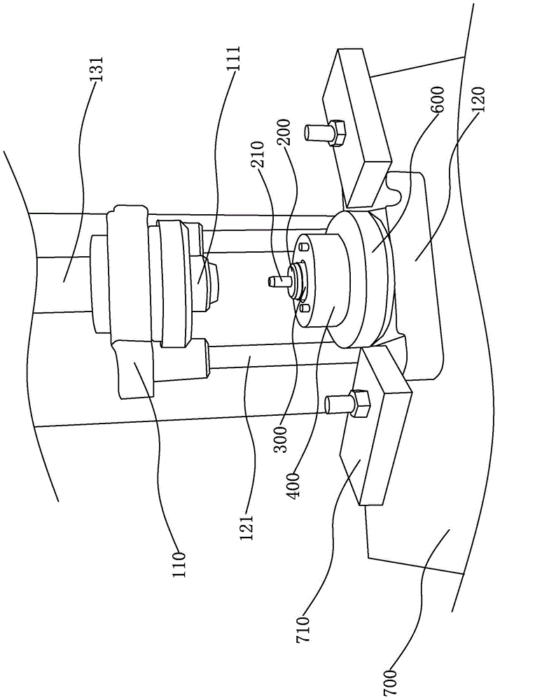
[0030] Such as figure 1 , figure 2 As shown, a commutator pneumatic bending machine of the present invention includes a stand 100, and on the vertical outer wall of the stand 100, an upper fixing plate 110 and a lower fixing plate 120, a first Cylinder 130 and second cylinder 140, the first cylinder 130 is vertically fixed to the upper end of the stand 100, the first piston rod 131 of the first cylinder 130 is fixed to the fixing plate, and a pressure head is arranged on the lower surface of the upper fixing plate 110 111. A commutator bending device is arranged on the lower fixing block.

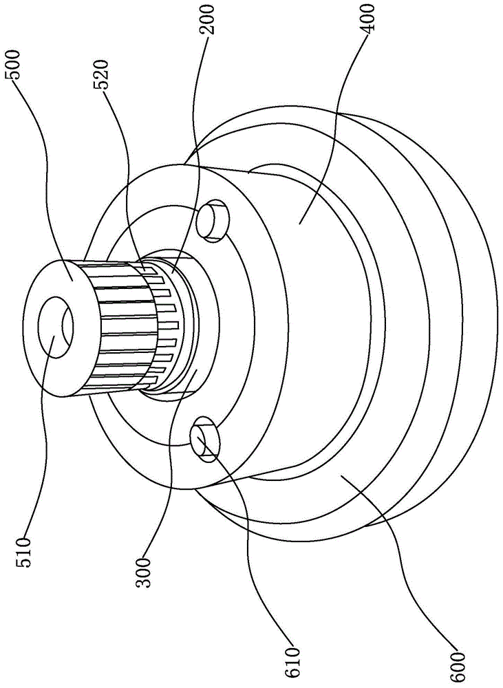
[0031] Such as Figure 3 to Figure 6 As shown, the bending device includes a mounting base 200, a bending sleeve 300 and a bending...


PUM


Abstract

The invention provides a pneumatic bending machine for a reverser, and belongs to the technical field of the reverser. The pneumatic bending machine solves the technical problems that the size of the existing bending machine is large, the structure is complicated, and the forming precision is high. The pneumatic bending machine for the reverser comprises a vertical seat, wherein an upper fixing plate and a lower fixing plate are arranged on the vertical seat, a reverser bending device is arranged on the lower fixing block, the bending device comprises an installing seat, a bent sleeve and a bent round disc, a first outer conical surface is arranged on the installing seat, the reverser is provided with a bent part abutted against the first outer conical surface, the bent sleeve is arranged on the installing seat in a sleeving way, the bent round disc is arranged on the bent sleeve in a sleeving way, the bent part is bent through the first outer conical surface, the bent sleeve and the bent round disc, and in addition, an included angle between the bent part and the reverser is smaller than 90 degrees. The pneumatic bending machine has the advantages that the size is small, the structure is compact, the forming efficiency is improved, each bending device singly performs bending processing on the reverser, the swinging cannot be generated in the processing process, and the forming precision of each bending device is higher.

Description

technical field [0001] The invention belongs to the technical field of commutators and relates to a pneumatic bending machine for commutators. Background technique [0002] The commutator is a part of the DC permanent magnet series motor in order to allow the motor to continue to rotate. It is surrounded by multiple contact pieces to form a circle. Between the use environment and its own work needs, each contact piece is commutated After the commutator is formed, it needs to be bent outward to form a hook, and the angle between the hook and the outer surface of the commutator is less than 90 degrees. [0003] The traditional commutator hook is generally composed of multiple processes, and each process needs to be equipped with corresponding equipment, and each set of equipment is operated by a corresponding operator, which leads to low processing efficiency and high processing cost. Therefore, people invented A forming device specially used for forming commutator hooks has ...

Claims


Application Information

Patent Timeline
Patent Type & Authority Applications(China)
IPC IPC(8): B21D11/00B21D11/22
CPCB21D11/00B21D11/22
Inventor 王国夫孙瑞娣蒋其丰陈岳祥
Owner HUARUI ELECTRICAL APPLIANCE
Features
  • R&D
  • Intellectual Property
  • Life Sciences
  • Materials
  • Tech Scout
  • Unparalleled Data Quality
  • Higher Quality Content
  • 60% Fewer Hallucinations
Learn More