A gas-hydraulic pressurized self-piercing riveting machine

A gas-liquid pressurized, self-piercing riveting technology, applied in the field of machinery manufacturing equipment, can solve the problems of complex riveting process, fatigue strength reduction, high-strength material temperature sensitivity, etc., to achieve small structural space occupation area, low production cost, The effect of fast riveting speed

Active Publication Date: 2016-08-24
EAST CHINA JIAOTONG UNIVERSITY
View PDF5 Cites 2 Cited by
  • Summary
  • Abstract
  • Description
  • Claims
  • Application Information

AI Technical Summary

Problems solved by technology

The connection of these light materials and steel and the connection between each other have always had problems such as insurmountable or difficult to ensure the quality and performance of the connection using traditional welding methods: some high-strength materials are sensitive to temperature effects. Local overheating is easy to occur during the process, resulting in a decrease in fatigue strength; plates with surface coatings or non-conductive organic protective layers should not be connected by welding; plates with poor weldability such as aluminum alloys, the connection effect of spot welding is not good. ideal
The traditional riveting process requires pre-punching the riveting material and then connecting with rivets. Such riveting process is complex, poor in appearance, low in efficiency and difficult to automate

Method used


Image

  • A gas-hydraulic pressurized self-piercing riveting machine
  • A gas-hydraulic pressurized self-piercing riveting machine
  • A gas-hydraulic pressurized self-piercing riveting machine

Examples


Embodiment Construction

[0041] The present invention will be further described below in conjunction with the accompanying drawings.

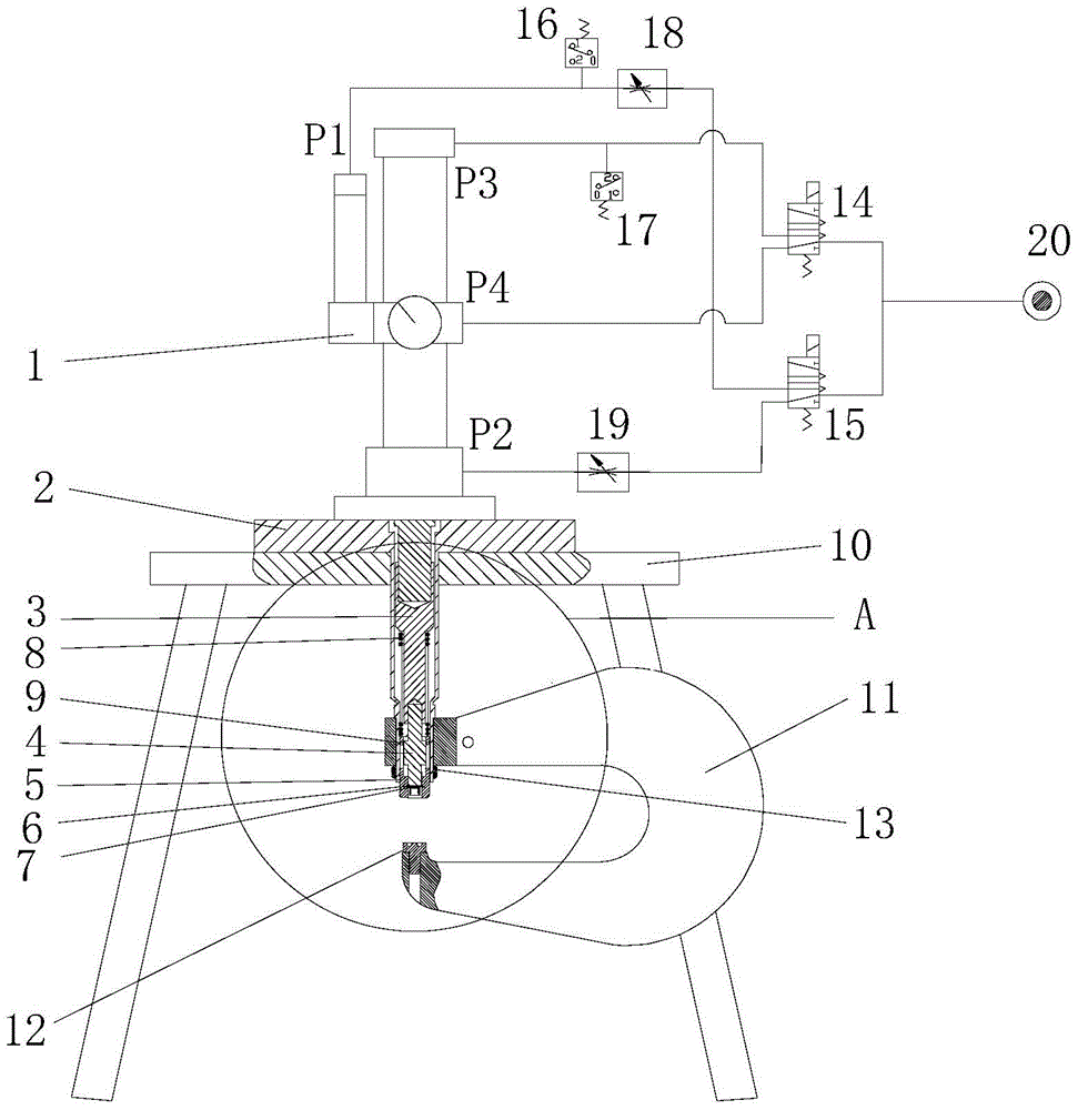
[0042] figure 1 It is a structural schematic diagram of the present invention, a gas-liquid pressurized self-piercing riveting machine, including a gas-liquid pressurized control system, a self-piercing riveting mechanism, a circuit control system and a support seat, the gas-liquid pressurized control system includes a gas-liquid pressurized Pressure cylinder 1, compressed air pump 20, 2-position 5-way reversing valve A14, 2-position 5-way reversing valve B15, speed regulating throttle valve 18, 19, normally open air pressure control switch 16, normally closed air pressure Control the switch 17 and the air pipe, the gas-liquid booster cylinder 1 is connected to the self-piercing riveting mechanism; the compressed air pump 20 is connected to the two-position five-way reversing valve A14 and the two-position five-way reversing valve B15 through the air pipe, and the two-...


PUM


Abstract

A pneumohydrualic self-piercing riveting machine comprises a pneumohydraulic control system, a self-piercing riveting mechanism, a support seat and a circuit control system. The pneumohydraulic control system comprises a pneumohydraulic cylinder, a compressed air pump and various control valves. The self-piercing riveting mechanism comprises a pneumohydraulic cylinder support, an upper punch, a lower punch, a C-shaped frame and a mold etc. The pneumohydraulic control system is connected with the self-piercing riveting mechanism through the pneumohydraulic cylinder and is arranged on the support seat integrally. The pneumohydraulic self-piercing riveting machine has the advantages of simple structure, low production cost, small structure-space occupation area, safety, reliability and the like. The circuit control system is simple and easy to realize, and convenient to operate. The pneumohydraulic self-piercing riveting machine has the advantages of full-automatic riveting process, high riveting speed and efficiency and continuous operation. By replacing the punches and the mold, the pnumohydraulic self-piercing riveting machine can be used for riveting of tubular rivets, tubular rivets with flanges, oval tubular rivets and no rivets.

Description

technical field [0001] The invention belongs to the technical field of mechanical manufacturing equipment, and relates to riveting equipment. Background technique [0002] As the world's energy becomes increasingly tense, people increasingly use lightweight materials to reduce their own weight in vehicles, trains, airplanes and other means of transportation. The connection of these light materials and steel and the connection between each other have always had problems such as insurmountable or difficult to ensure the quality and performance of the connection using traditional welding methods: some high-strength materials are sensitive to temperature effects. Local overheating is easy to occur during the process, resulting in a decrease in fatigue strength; plates with surface coatings or non-conductive organic protective layers should not be connected by welding; plates with poor weldability such as aluminum alloys, the connection effect of spot welding is not good. ideal....

Claims


Application Information

Patent Timeline
Patent Type & Authority Patents(China)
IPC IPC(8): B21J15/22B21J15/28
CPCB21J15/025B21J15/22B21J15/30
Inventor 黄志超谢春辉赖家美周泽杰张永超占金青黄薇
Owner EAST CHINA JIAOTONG UNIVERSITY
Why Eureka
Try Eureka