End surface grooving device
A grooving and end face technology, which is applied to turning equipment, turning equipment, metal processing equipment, etc., can solve the problems of difficult size guarantee, time-consuming and labor-intensive problems, and achieve the effect of improving processing efficiency and processing accuracy and reducing investment in fixed assets
- Summary
- Abstract
- Description
- Claims
- Application Information
AI Technical Summary
Problems solved by technology
Method used
Image

Examples
Embodiment 1
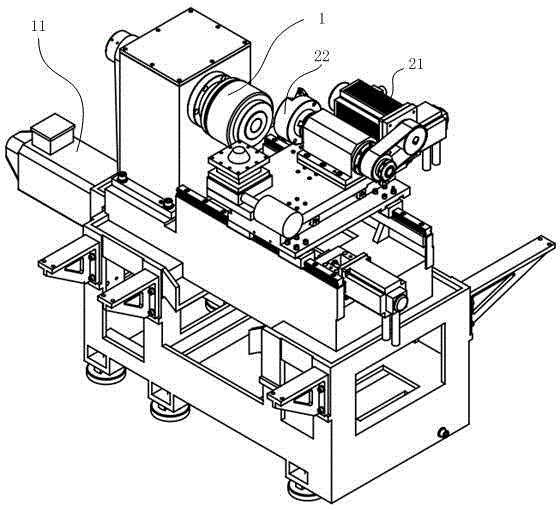
[0013] Embodiment 1, with reference to appended Figure 1-4 .
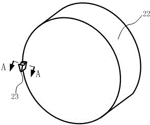
[0014] An end face grooving device comprises a grooving frame, a grooving motor 21 installed on the grooving frame and a cutter head 22 driven by the grooving motor 21; Front and rear, left and right, and up and down displacements, a grooving knife 23 is installed on the cutterhead 22, and the spindle motor 11 and the grooving motor 21 are controlled by a synchronous device so that the angular velocity ratio of the spindle chuck 1 and the cutterhead 22 is 1:2. The grooving knife 23 is installed on the edge of the end face of the cutter head 22 relative to the spindle chuck 1 . The cross-sectional shape of the grooving knife 23 is an isosceles inverted trapezoid.
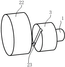
[0015] In the initial state, the grooving knife 23 is separated from the workpiece 3 to be processed. After the processing starts, as the cutterhead 22 approaches the workpiece 3 horizontally, the grooving knife 23 also begins to approach the workpiece...
Embodiment 2
[0016] Embodiment 2, with reference to appended Figure 1-4 .
[0017] Others are the same as the embodiment, except that the ratio of the angular velocity of the spindle chuck 1 to the angular velocity of the cutter head 22 is 1:4, and two evenly distributed linear grooves are cut from shallow to deep on the workpiece 3 to be processed.
Embodiment 3
[0018] Embodiment 3, with reference to appended Figure 1-5 .
[0019] Others are the same as the embodiment, except that the ratio of the angular velocity of the spindle chuck 1 to the angular velocity of the cutter head 22 is 1:6, and three evenly distributed linear grooves are cut from shallow to deep on the workpiece 3 to be processed.
[0020] According to experimental monitoring, the straightness of the grooves processed on the workpiece 3 to be processed can be controlled below 0.01mm, and the angle error between the grooves can be controlled below 0.005mm. The production frequency can reach 20 pieces / min, which is 3-4 times of the old equipment.
PUM
 Abstract
Description
Claims
Application Information