
Clamp

A technology of clamps and jaws, which is applied in the field of clamps that produce fine positioning and clamping effects on rods. It can solve the problems of reducing the reliability of clamp sleeves and unstable swing effects, achieving reliable action effects and improving structural strength.

Inactive Publication Date: 2015-04-29
创研精密股份有限公司
View PDF1 Cites 0 Cited by
  • Summary
  • Abstract
  • Description
  • Claims
  • Application Information

AI Technical Summary

Problems solved by technology

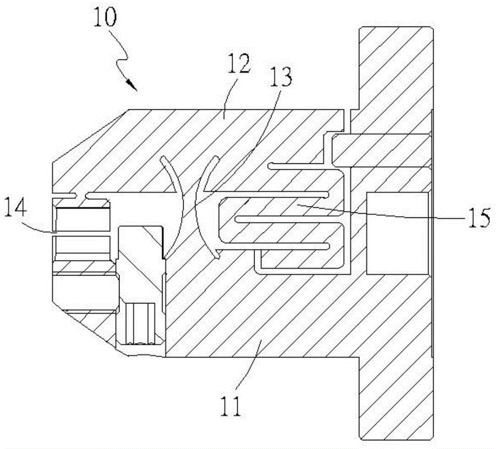
[0008] In the clamp sleeve disclosed in Taiwan Patent Publication No. 200639006, the bending and deformation of the entire elastically deformable wall 13 causes the movable element 12 to move toward the rigid element 11 relative to the end forming the jaw 14. Pressing against, or causing the movable element 12 to displace in the direction opposite to the rigid element 11 relative to the end forming the jaw 14, but during the swinging process of the movable element 12, the fulcrum of the movable element 12 will swing with it Different degrees fall on different parts of the entire elastically deformable wall 13, making the swing effect generated by the movable element 12 extremely unstable, so that the reliability of the clamp sleeve is greatly reduced

Method used


Image

  • Clamp
  • Clamp
  • Clamp

Examples


Embodiment Construction

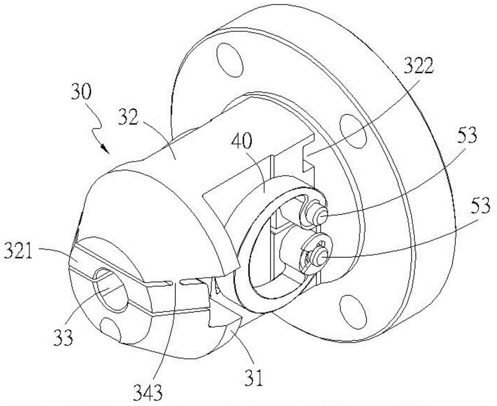
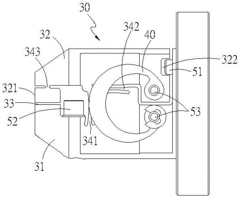
[0055] Please cooperate with the reference Figure 2 to Figure 5 As shown in the related structural diagram of the fixture of the first embodiment of the present invention, the fixture of the present invention is basically formed on a body 30 with a rigid part 31 and a movable part 32 with a predetermined distance, and the head end of the block 30 There is formed a clamping opening 33 between the rigid part 31 and the movable part 32 for the rod 20 to be clamped, and at least one connection with the rigidity is provided at the other end of the block 30 relative to the clamping opening 33. The elastic element 40 between the component 31 and the movable component 31 normally provides an active force to make the end of the movable component 32 located at the jaw 33 press against the rigid component 331 .

[0056]The key point of the present invention is: this block 30 forms a first chain belt 341 that is vertically connected between the rigid part 31 and the movable part 32 at th...


PUM


Abstract

The invention discloses a clamp. The clamp is characterized in that a block body is machined to form a rigid component and a movable component with a preset distance reserved between the rigid component and the movable component; a clamping hole allowing a to-be-clamped rod piece to extend between the rigid component and the movable component is formed in the head end; at least one elastic element connected between the rigid component and the movable component is arranged at the other end, opposite to the clamping hole, of the block body; furthermore, a first chain belt perpendicularly connected between the rigid component and the movable component is integrally formed at the position, opposite to the inner side of the clamping hole, of the block body, and a second chain belt horizontally connected to the rigid component is integrally formed at the joint of the first chain belt and the movable component. Therefore, the connection between the movable component and the rigid component can be realized under the action of the first chain belt and the second chain belt, and the movable component is limited to swing around the joint, serving as a pivot, of the first chain belt and the second chain belt, so that a relatively stable and reliable operating effect can be achieved.

Description

technical field [0001] The invention relates to a clamp, in particular to a clamp that can be used to produce a fine positioning and clamping effect on a rod. Background technique [0002] Press, the development of micro-cutting technology mainly depends on the support of micro-cutting tool technology; in principle, the tool suitable for micro-cutting should at least have: small local feature scale, sharp cutting edge, good surface quality, high strength, good rigidity, And good wear resistance and other characteristics, and its requirements for its own dimensional accuracy and accuracy are relatively high. [0003] Therefore, in the process of processing and grinding the body of the micro-cutting tool, it is especially necessary to clamp and fix the body of the micro-cutting tool, so as to avoid affecting the dimensional accuracy of the micro-cutting tool due to the movement of the body of the micro-cutting tool. In addition, in order to maintain the processing capacity of...

Claims


Application Information

Patent Timeline
Patent Type & Authority Applications(China)
IPC IPC(8): B23B31/10B23Q3/12B23B31/02
CPCB23Q3/00B23Q2703/10
Inventor 郭肇源
Owner 创研精密股份有限公司
Learn More