The processing method of the central measuring tool for detecting the driving disc fixture when processing the steam turbine blade

A steam turbine blade and processing method technology, which is applied to metal processing machinery parts, manufacturing tools, metal processing equipment, etc., can solve the problems of low working precision and difficult processing of central measuring tools, and achieve saving of component materials and processing costs, reducing The effect of stress deformation

Active Publication Date: 2016-11-23
HARBIN TURBINE
View PDF6 Cites 0 Cited by
  • Summary
  • Abstract
  • Description
  • Claims
  • Application Information

AI Technical Summary

Problems solved by technology

[0003] The purpose of the present invention is to solve the problem of difficult processing and low working precision of the existing center measuring tool, and to provide a center measuring tool and its processing method for detecting driving disc clamps when processing steam turbine blades

Method used


Image

  • The processing method of the central measuring tool for detecting the driving disc fixture when processing the steam turbine blade
  • The processing method of the central measuring tool for detecting the driving disc fixture when processing the steam turbine blade
  • The processing method of the central measuring tool for detecting the driving disc fixture when processing the steam turbine blade

Examples


specific Embodiment approach 1

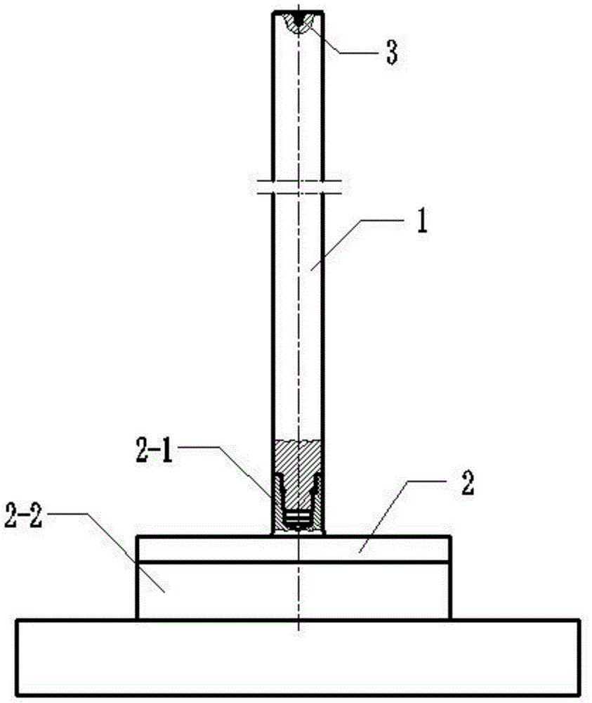
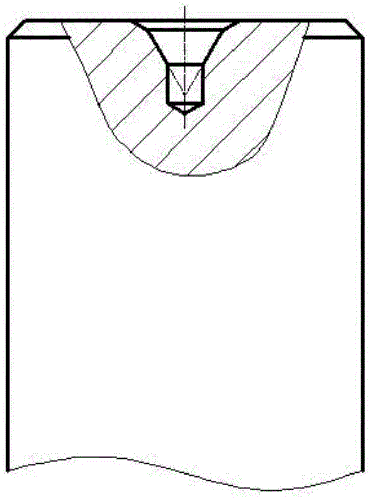
[0020] Specific implementation mode 1: In this embodiment, when processing steam turbine blades, the central measuring tool for detecting the driving disc fixture is composed of an extension rod 1 and a measuring body 2, wherein the measuring body 2 is composed of a blade root 2-2 and a cylindrical boss 2-1, and the measuring tool The blade root 2-2 below the specific 2 has the same size and shape as the simulated blade root, and the top of the specific 2 is a cylindrical boss 2-1, and a threaded hole is opened in the cylindrical boss 2-1, and an extension rod 1 is cylindrical, and the extension rod 1 is connected with the cylindrical boss 2-1 on the measuring body 2 through threads, and a central hole 3 is opened at the top of the extension rod 1 .

specific Embodiment approach 2

[0021] Embodiment 2: This embodiment differs from Embodiment 1 in that the length of the extension rod 1 is 600-800 mm.

specific Embodiment approach 3

[0022] Embodiment 3: This embodiment differs from Embodiment 1 in that the diameter of the extension rod 1 is 40 mm.


PUM

PropertyMeasurementUnit
heightaaaaaaaaaa

Abstract

The invention relates to a measuring tool and a machining method thereof, particularly to a driving disc clamp detection measuring tool during machining of steam turbine blades and a machining method thereof. The driving disc clamp detection measuring tool during machining of the steam turbine blades and the machining method thereof are used for solving the problems of machining difficulty and low working precision of existing central measuring tools. The driving disc clamp detection measuring tool during machining of the steam turbine blades comprises an extension bar and a measuring tool body; the blade root portion at the lower end of the measuring tool body is identical in size and shape to the root of a blade to be simulated; the cylindrical boss of the measuring tool body is provided with a threaded hole, and the extension bar is connected with the cylindrical boss of the measuring tool body through threads. The machining method of the driving disc clamp detection measuring tool during machining of the steam turbine blades comprises, firstly, rough-milling out the measuring tool body and the extension bar, and performing quenched-tempered heat treatment on the measuring tool body and the extension bar; secondly, drilling out the threaded hold inside the cylindrical boss, and turning out the external threads of the extension bar; lastly, preforming finish turning after the measuring tool body and the extension bar are assembled to complete machining of the central measuring tool. According to the driving disc clamp detection measuring tool during machining of the steam turbine blades, the extension bar and the measuring tool body are of an assembly type structure, so that the machining time can be saved, and a locating degree within 0.03 mm can be reached.

Description

technical field [0001] The invention relates to a measuring tool and a processing method thereof, in particular to a special tool for detecting the working position of a drive disc clamp and a processing method thereof. Background technique [0002] The center measuring tool is a special tool used to detect the working position of the driving disc fixture, so as to ensure that the steam turbine blades are positioned in the correct working position, ensure the normal processing of the blades, and avoid the generation of waste products. The structure of the existing central measuring tool is an integrated structure. When the existing integrated central measuring tool is processed, the blank is first forged. The lower end of the blank is a cuboid, and the upper end is cylindrical. This not only wastes materials, but also lengthens the cylinder when processing the blade root tooth profile. The rod affects the positioning and clamping. After the blank is forged, it is heat-treate...

Claims


Application Information

Patent Timeline
Patent Type & Authority Patents(China)
IPC IPC(8): B23Q17/00B23P15/00
CPCB23P15/00B23Q17/003
Inventor 孙盛丽王国庆宋光伟胡卫杰孙述军
Owner HARBIN TURBINE
Why Eureka
Try Eureka