General clamp for abrasive flow polishing of complicated hole surface

An abrasive flow and hole surface technology, applied in the direction of grinding workpiece supports, can solve the problems of fixture design, increased manufacturing workload, poor economy, waste of manpower and material resources, etc., and achieves low cost, universal fixtures, and wide adaptive effect

Inactive Publication Date: 2015-04-29
CHANGCHUN UNIV OF SCI & TECH
View PDF6 Cites 39 Cited by
  • Summary
  • Abstract
  • Description
  • Claims
  • Application Information

AI Technical Summary

Problems solved by technology

[0004] The invention discloses a universal jig for complex hole surface abrasive flow polishing to solve the problem that when there are many types of parts to be polished in the prior art, the nu

Method used


Image

  • General clamp for abrasive flow polishing of complicated hole surface
  • General clamp for abrasive flow polishing of complicated hole surface
  • General clamp for abrasive flow polishing of complicated hole surface

Examples


Example Embodiment

[0014] The embodiments of the present invention will be described in detail below with reference to the accompanying drawings.

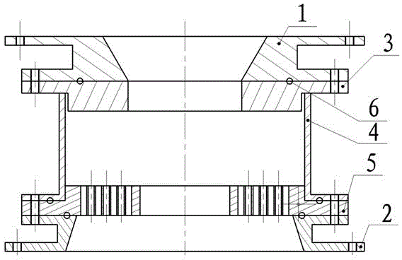
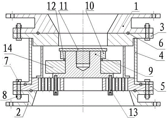
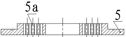
[0015] Examples of the present invention figure 1 , figure 2 , image 3 , Figure 4 As shown, this embodiment includes a clamp body, an embedded module, and bolts 13; the clamp body includes a lower guide sleeve 1, an upper guide sleeve 2, a lower pressure plate 3, a sleeve 4, an upper pressure plate 5, a sealing ring 6, and a bolt 7. , nut 8; the upper pressure plate 5 has a built-in module connection hole 5a, and the abrasive flow channel hole 5b distributed in the circumferential radial direction; the upper pressure plate 5 abrasive flow channel hole 5b is axially parallel to the polished surface of the polished workpiece 14; The sleeve 2, the upper pressure plate 5 and the sleeve 4 are tightly connected; the sealing ring 6 is installed between the joint surface between the lower guide sleeve 1 and the lower pressure plate 3, the lower guide s...


PUM


Abstract

The invention discloses a general clamp for abrasive flow polishing of a complicated hole surface. The general clamp comprises a clamp body and one or more embedded modules; the clamp body is provided with uniformly distributed threaded holes in the peripheral direction; the clamp body comprises a lower pressing plate, a sleeve, an upper pressing plate and a sealing ring; the upper pressing plate and the sleeve are connected in a fastened manner; the lower pressing plate is connected with the sleeve; the upper pressing plate is provided with embedded module connecting holes and abrasive flow channel holes; the embedded modules are arranged in the clamp body; the embedded modules are detachably connected with the upper pressing plate in a fastened manner; the embedded modules compresses a non-polishing surface of a polished workpiece; the upper pressing plate is provided with the embedded module connecting holes uniformly distributed in the peripheral direction, and the embedded module connecting holes are used for connecting with different embedded modules; the abrasive flowing channel holes of the upper pressing plate are axially parallel to the polishing surface of the polished workpiece; the abrasive flow circulates in the abrasive flow channel holes in the part, which is not pressed and covered, of the upper pressing plate; when the surface of the polished workpiece is a curved surface, a columnar surface or a hole parallel to the direction of the abrasive flow, the embedded modules of corresponding shapes are replaced and recombined according to the appearance surface of the polished workpiece.

Description

technical field [0001] The invention belongs to the technical field of ultra-precision machining, and relates to a general fixture for abrasive flow polishing with complex hole surfaces, in particular to a general fixture for complex hole surface abrasive flow polishing with built-in modules; it is especially suitable for various types of polished parts, A variety of hole, surface abrasive flow polishing, universal fixture. Background technique [0002] Abrasive Flow Machining (AFM) is a new technology for surface polishing and deburring of workpieces with a fluid viscoelastic material composed of a polymer carrier and abrasive. Extrusion honing or abrasive flow machining. In the process of abrasive flow polishing, the fixture is a very important part, which is related to the quality and efficiency of the process. Abrasive flow fixtures are used to hold the workpiece and guide the abrasive to the surface to be machined. In addition, the fixture also acts as a sealing flow...

Claims


Application Information

Patent Timeline
IPC IPC(8): B24B41/06
CPCB24B41/06
Inventor 刘薇娜陈莎莎杨立峰刘志刚苏东楠张镇
Owner CHANGCHUN UNIV OF SCI & TECH
Why Eureka
Try Eureka