a die-cutting machine

A die-cutting machine and die-cutting technology, applied in the direction of metal processing, etc., can solve the problems of low working efficiency, unfavorable market competitiveness, inconvenient disassembly and replacement of die-cutting machines, so as to improve the effect of die-cutting and increase market competition force, quick disassembly and replacement

Active Publication Date: 2016-08-17
DONGGUAN WARTON PRINTING
View PDF6 Cites 5 Cited by
  • Summary
  • Abstract
  • Description
  • Claims
  • Application Information

AI Technical Summary

Problems solved by technology

The current die-cutting machine has disadvantages such as inconvenient disassembly and replacement, high hidden dangers in operation safety, and unsatisfactory die-cutting effect, which leads to low working efficiency of the entire die-cutting machine, which is not conducive to improving market competitiveness.

Method used


Image

  • a die-cutting machine
  • a die-cutting machine

Examples


Embodiment Construction

[0018] The present invention will be further described below in conjunction with specific embodiments and drawings.

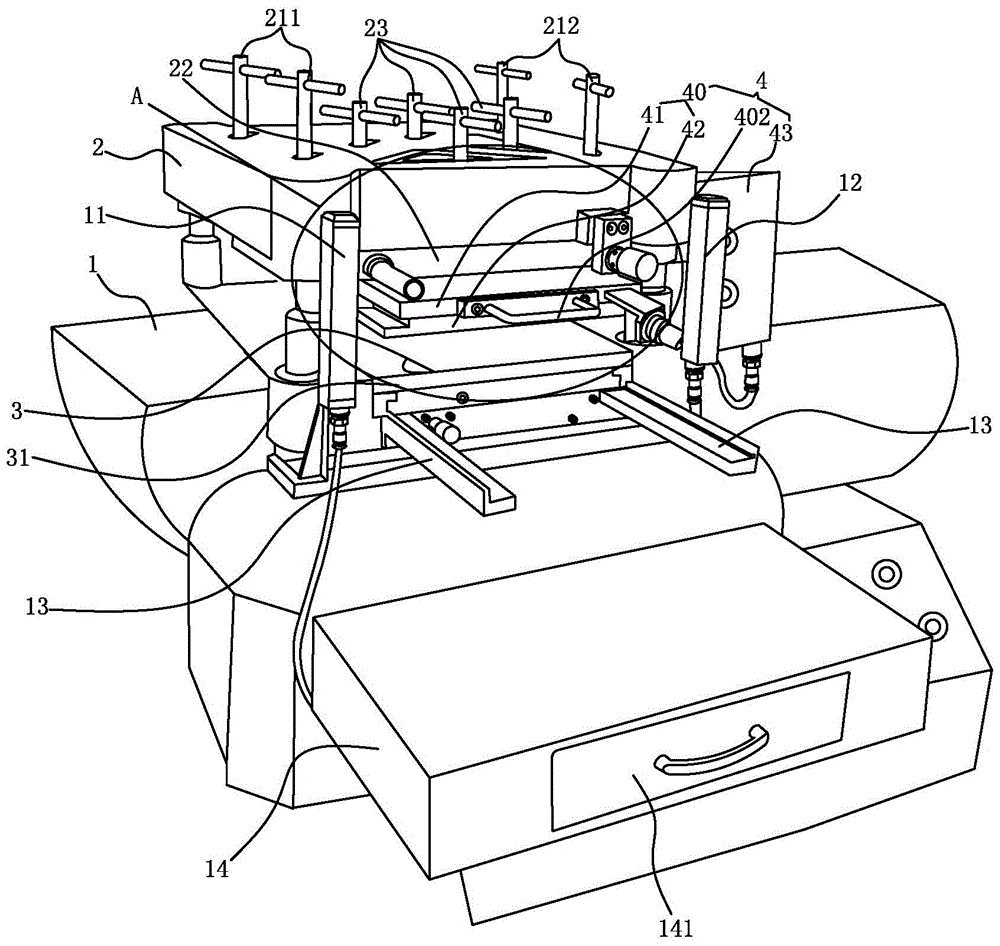
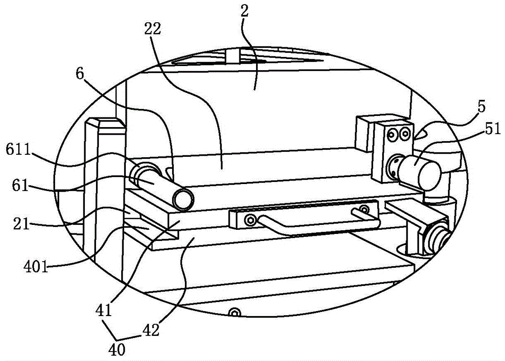
[0019] see figure 1 , 2 As shown, it is a die-cutting machine, which includes: a machine base 1, a punching head installed on the machine base 1, a driving device installed in the machine base 1 and used to drive the punching head 2 to realize a punching action, The base 1 is equipped with a lower mold base assembly 3; the lower end of the punch head 2 is provided with an upper mold base assembly 4 that matches the lower mold base assembly 3, and the upper mold base assembly 4 and the lower mold base assembly There is a gap between 3, when the material is transported through the gap formed between the upper die base assembly 4 and the lower die base assembly 3, the driving device drives the punch head 2 to punch down, and the upper die base assembly 4 The punching head 2 punches downwards and cooperates with the lower mold base assembly 3 to realize the die cuttin...


PUM


Abstract

The invention discloses a die cutting machine comprising a base, a punching head installed on the base and a drive device which is installed in the base and which is used for driving the punching head to implement the punching actions. The die cutting machine is characterized in that a lower die seat component is installed on the base; the lower end of the punching head is provided with a first slide rail, a second slide rail and an upper die seat component which is installed between the first slide rail and the second slide rail in an inserted assembling manner and which matches with the lower die seat component; the punching head is provided with a first locking component and a second locking component which are used for locking the upper die seat component; the upper die seat component comprises a heat die cutting seat, an upper cavity installed at the lower end of the cutting seat and a power box connected with the die cutting seat electrically, and the power box is installed on the base and is connected to the die cutting seat through a guide wire. The die cutting machine is safe to operate and convenient to disassemble and change and has ideal die cutting effect, high operating efficiency and high market competitiveness.

Description

Technical field: [0001] The invention relates to the technical field of die-cutting machine products, in particular to a die-cutting machine with safe operation, simple disassembly and assembly, convenient replacement and ideal die-cutting effect. Background technique: [0002] Die Cutting Machine (Die Cutting Machine) is also called beer machine, cutting machine, CNC punching machine, which is mainly used in the corresponding non-metallic materials, self-adhesive, double-sided tape, electronics, mobile phone pads and product packaging and decoration industries The die-cutting (full-broken, half-broken), indentation and bronzing operations of trademarks, cartons, greeting cards, etc. in the paper are important equipment for post-press packaging processing and shaping. [0003] The working principle of the die-cutting machine is to use steel knives, hardware molds, steel wires or steel plates to engrave a template, and apply a certain pressure through the embossing plate to roll and...

Claims


Application Information

Patent Timeline
Patent Type & Authority Patents(China)
IPC IPC(8): B26F1/44B26D7/10B26D7/22
CPCB26D7/10B26D7/22B26D7/26B26D2007/2607B26F1/40B26F1/44
Inventor 罗攀峰宋世权孙伟
Owner DONGGUAN WARTON PRINTING
Why Eureka
Try Eureka