
Temperature-controllable real-time temperature acquisition system for heat transfer coefficient evaluation

A real-time acquisition and heat transfer coefficient technology, applied in the field of material heat transfer coefficient research and testing, can solve the problems of inconvenient popularization and application, high cost, high energy consumption, etc., to avoid electric shock and thermal burns, low cost, and low energy consumption Effect

Active Publication Date: 2015-09-09
SICHUAN UNIV
View PDF4 Cites 5 Cited by
  • Summary
  • Abstract
  • Description
  • Claims
  • Application Information

AI Technical Summary

Problems solved by technology

Large-area heating consumes a lot of energy and costs, making it difficult to popularize and apply

Method used


Image

  • Temperature-controllable real-time temperature acquisition system for heat transfer coefficient evaluation
  • Temperature-controllable real-time temperature acquisition system for heat transfer coefficient evaluation
  • Temperature-controllable real-time temperature acquisition system for heat transfer coefficient evaluation

Examples


Embodiment 1

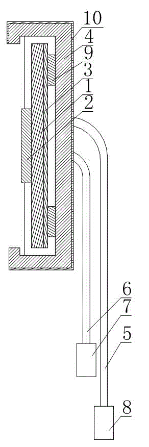
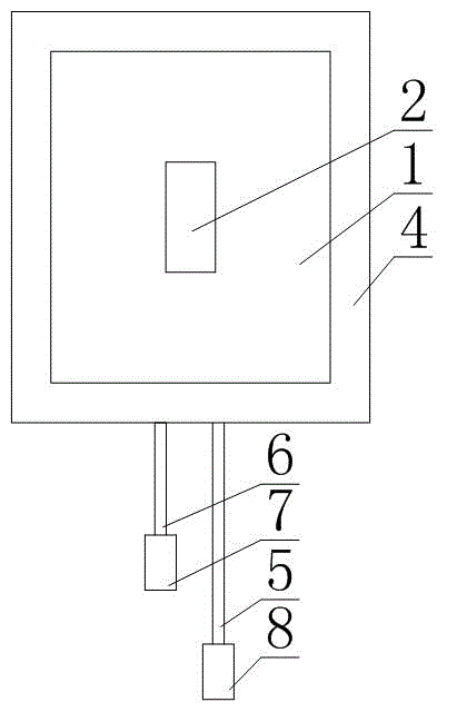
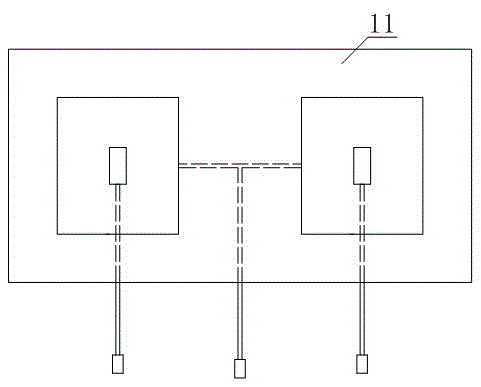
[0029] Such as figure 1 and figure 2 As shown, a temperature real-time collection system for heat transfer coefficient evaluation that is convenient for temperature control includes a silicone rubber connecting plate 11 and two or more temperature collection devices, where the temperature collection device includes a heating plate 1, a temperature sensor 2, and a silicone rubber The opening box 4, the sensor connector 7 and the power cord connector 8. The rear end of the silicone rubber opening box 4 is fixed on the silicone rubber connecting plate 11 and the opening is arranged on the front side. The heating plate 1 and temperature of each temperature collection device The sensors 2 are all arranged in the silicone rubber opening box 4, the heating plate 1 is arranged parallel to the back plate of the silicone rubber opening box 4, and the temperature sensor 2 is arranged on the front side of the heating plate 1 and its probe is facing in front of the silicone rubber opening bo...

Embodiment 2

[0034] This embodiment further defines the following on the basis of Embodiment 1: The temperature collection device of this embodiment further includes a heat-insulating fixing plate 3, wherein the heat-insulating fixing plate 3 is fixed in the silicone rubber opening box 4 and located on the heating plate Between 1 and the back plate of the silicone rubber open box 4, the heating sheet 1 is fixed on the heat insulation fixing plate 3.

Embodiment 3

[0036] This embodiment further defines the following on the basis of Embodiment 2: The power cord 5 of this embodiment passes through the heat insulation fixing plate 3, the back plate of the silicone rubber opening box 4, and the silicone rubber connecting plate 11 in sequence, and the signal transmission line 6 Pass through the back plate of the silicone rubber opening box 4 and the silicone rubber connecting plate 11 in sequence. In this way, the power line 5 and the signal transmission line 6 of the present embodiment can be effectively fixed, thereby avoiding entanglement.


PUM

PropertyMeasurementUnit
thicknessaaaaaaaaaa

Abstract

The invention discloses a temperature-controllable real-time temperature acquisition system for heat transfer coefficient evaluation. The temperature-controllable real-time temperature acquisition system comprises a silicone rubber connecting plate and more than two temperature acquisition devices, wherein each temperature acquisition device comprises a heating plate, a temperature sensor, a silicone rubber opening box, a sensor connector and a power line connector, the rear end of the silicone rubber opening box is fixed on the silicone rubber connecting plate and the opening of the silicone rubber opening box is formed in the front side, the heating plate and the temperature sensor are both arranged in the silicone rubber opening box, the heating plate is parallel to a back plate of the silicone rubber opening box, the temperature sensor is arranged on the front side of the heating plate, a probe of the temperature sensor right faces the opening in the front side of the silicone rubber opening box, the power line connector is connected with the heating plate through a power line penetrating through the silicone rubber opening box, and the sensor connector is connected with the temperature sensor through a signal transmission line penetrating through the silicone rubber opening box. The temperature-controllable real-time temperature acquisition system is simple in integral structure, low in cost and convenient to implement, mount and carry, heats a tested point locally during application, and is low in energy consumption and convenient to popularize and apply.

Description

Technical field [0001] The invention relates to the field of material heat transfer coefficient research and testing, in particular to a temperature real-time acquisition system for heat transfer coefficient evaluation convenient for temperature control. Background technique [0002] At present, when calculating the heat transfer coefficient of curtain wall glass, building frame and composite material board, it is necessary to obtain the temperature value of the inner and outer surface of the measured point and the wind speed data of the outer surface, and then calculate the inner and outer surface of the measured point according to the obtained temperature value of the inner and outer surface The temperature difference of the surface, and then the temperature difference data of the inner and outer surfaces combined with the wind speed data of the outer surface to calculate the heat transfer coefficient of the measured material and structure. [0003] In order to obtain the necessa...

Claims


Application Information

Patent Timeline
Patent Type & Authority Applications(China)
IPC IPC(8): G01N25/20
Inventor 王志宇王清远
Owner SICHUAN UNIV
Learn More