Check patentability & draft patents in minutes with Patsnap Eureka AI!

Multi line cutting machine swing drive structure

A technology of multi-wire cutting machine and drive structure, which is applied in the direction of working accessories, fine working devices, stone processing equipment, etc., can solve the problems of large volume and moment of inertia of the swing head, reduced fatigue life of parts, complex structure assembly requirements, etc. Achieve the effects of avoiding poor sealing problems, reducing structural weight, and operating responsively

Inactive Publication Date: 2015-04-29
常州贝斯塔德机械股份有限公司
View PDF5 Cites 2 Cited by
  • Summary
  • Abstract
  • Description
  • Claims
  • Application Information

AI Technical Summary

Problems solved by technology

After the motor is converted by the reducer, the gear drive drives the slider to move on the arc guide rail. This structure has many intermediate conversion links, and various errors accumulate and are difficult to control, resulting in limited swing accuracy.
The power parts such as the motor and the reducer, the transmission parts such as the transmission shaft, the gear and the slider guide rail are all located above the swing head and connected together. The complex structure requires very high assembly requirements, and there is more moisture in the cutting room, which will affect the sealing and waterproof of the parts. Rust prevention puts forward higher requirements; the traditional structure of the swing head has a large volume and moment of inertia, which is not convenient for space arrangement and will greatly reduce the fatigue life of the parts under continuous working conditions

Method used


Image

  • Multi line cutting machine swing drive structure

Examples


Embodiment Construction

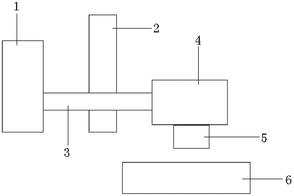
[0011] Such as figure 1 As shown, a swing drive structure for a multi-wire cutting machine described in the embodiment of the present invention includes: a transmission part 3, a power part 1 is installed at the front end of the transmission part 3, and a swing is installed at the rear end of the transmission part 3. Head 4, the vertical movement part 2 is installed in the middle of the transmission part 3; the workpiece sapphire rod 5 is clamped in the lower part of the swing head 4; the cutting mesh wire 6 is located directly below the swing head 4. This new structure reduces the links such as gear transmission and swinging guide rail sliders in the traditional swing mechanism, and can avoid the gap and error accumulation in the links, thereby greatly improving the precision of swing cutting; this structure combines the key power part and transmission part. Together with the up and down movement parts, they are all placed on one side of the swing head, which greatly simplifi...


PUM


Abstract

The invention relates to a multi line cutting machine swing drive structure comprising a transmission portion. The front end of the transmission portion is provided with a power portion,the rear end of the transmission portion is provided with a swing head, and the middle of the transmission portion is provided with a vertical moving portion; the lower portion of the swing head clamps a workpiece blue gem bar; cutting grid lines are located under the swing head. The structure has the advantages that the structure of the swing head is simplified greatly, the swing head can be placed outside a cutting chamber for tightness and water proofing, the structural weight of the swing head is reduced, the rotating inertia is reduced, and the operation reaction is more flexible; the size of the swing head is reduced, and the spatial arrangement of a machine is facilitated; the problem of poor tightness of key portions is avoided, and the service life of the mechanism components is prolonged; in addition, the structural operation is simple, the assembling and disassembling time of the swing mechanism is shortened effectively for workers, and the maintaining and repairing efficiency is improved.

Description

technical field [0001] The invention relates to a swing driving structure for a multi-wire cutting machine. Background technique [0002] At present, the swing structure on the traditional multi-wire cutting machine mostly adopts gear transmission and arc guide rail structure. After the motor is converted by the reducer, the gear drive drives the slider to move on the arc guide rail. There are many intermediate conversion links in this structure, and various errors accumulate and are difficult to control, resulting in limited swing accuracy. The power parts such as the motor and the reducer, the transmission parts such as the transmission shaft, the gear and the slider guide rail are all located above the swing head and connected together. The complex structure requires very high assembly requirements, and there is more moisture in the cutting room, which will affect the sealing and waterproof of the parts. Rust prevention puts forward higher requirements; the traditional s...

Claims


Application Information

Patent Timeline
IPC IPC(8): B28D5/04B28D7/00
CPCB28D5/042B28D5/0064
Inventor 岳伟殷华林戴安娜伊莲娟
Owner 常州贝斯塔德机械股份有限公司
Features
  • R&D
  • Intellectual Property
  • Life Sciences
  • Materials
  • Tech Scout
  • Unparalleled Data Quality
  • Higher Quality Content
  • 60% Fewer Hallucinations
Learn More