Rotary direct-driving arch breaking device

A driving device and arch-breaking technology, which is applied in the field of rotary direct-motion arch-breaking devices and auxiliary equipment, can solve the problems that can not completely eliminate the arching of tent materials, affect the normal production, and the limited area of ​​arch-breaking, etc., to improve the equipment installation Efficiency, facilitate on-site installation, eliminate workload effect

Active Publication Date: 2015-04-29
河南辉强机械设备有限公司
View PDF5 Cites 6 Cited by
  • Summary
  • Abstract
  • Description
  • Claims
  • Application Information

AI Technical Summary

Problems solved by technology

[0002] At present, most of the material temporary storage bins are conical, or the discharge section at the bottom is conical. During the temporary storage, the gravity of the material makes the extrusion force between adjacent materials, which causes the material to arch and block when it is discharged. Unable to flow down, which affects the normal production. Therefore, in the patent No. 201020109013X submitted by me, I proposed a solution, that is, using a hydraulic cylinder to poke the material. This solution can partially solve the above-mentioned arching problem , but for occasions with a large arching area, or for arching formed by sticky and wet materials, due to the limited area at the end of the poking device, the area of ​​the arching is also limited, and it is possible to form a poking hole only at the arching part However, the arching cannot be completely eliminated, so in this case, the problem of arching of the tent material cannot be completely eliminated

Method used


Image

  • Rotary direct-driving arch breaking device
  • Rotary direct-driving arch breaking device
  • Rotary direct-driving arch breaking device

Examples


Embodiment 1

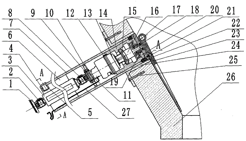
[0021] Example 1: see figure 1 , figure 2 , Figure 5 , The direct-acting drive device adopts an oil cylinder 3. The oil cylinder is connected to the base 1 through a hinged shaft 2. The outer wall of the oil cylinder barrel 38 is welded with three guide sliding blocks 6 along the cylinder axis. The outer surface of the guide sliding block and the inner surface of the arch breaking sleeve 7 With sliding fit, the cylinder piston rod 39 is connected to the connecting plate 11 through the inner hinge shaft 8 and the inner hinge shaft seat 9 with the connecting bolt 10, and the connecting plate is welded to the inner wall of the arch breaking sleeve. Use countersunk screws 21 to connect the bearing chamber inside the upper end of the broken arch sleeve. The rotary drive device is driven by an oil motor 13 with a reduction mechanism. The oil motor is fixed at one end of the bearing chamber 14 by a fastening bolt 12, and the oil motor output shaft is used The key is connected to the ...

Embodiment 2

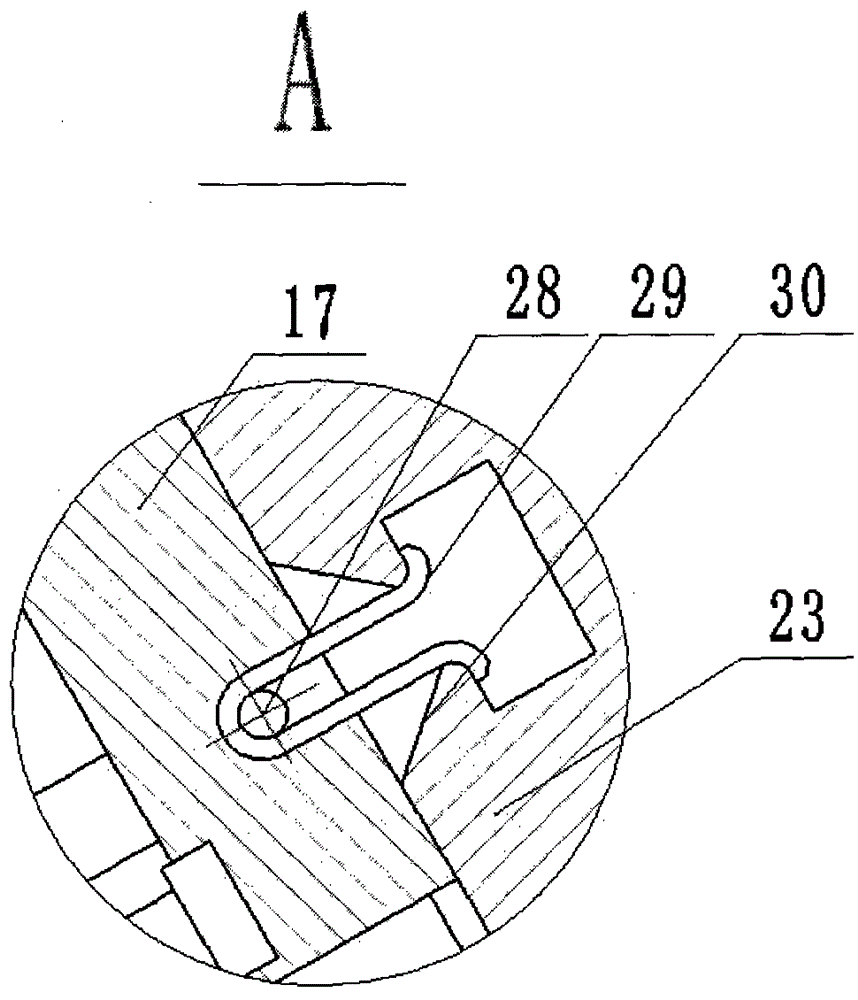
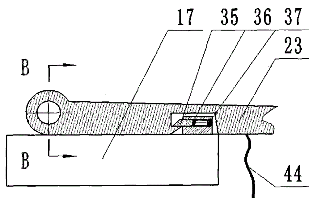
[0025] Example 2: see image 3 , Figure 4 In this embodiment, the swing locking device is composed of a locking pin 35, a pin seat 36, a spring 37, etc. The pin seat is welded to the revolving cover, and a tapered slot 30 is provided on the distance rod. When installing the arch breaking device, the distance rod is swung around the pin shaft by pulling the rope 44. When the locking pin enters the tapered slot on the distance rod after a certain angle, the spring is compressed and finally enters the tapered card. In the cavity at the upper part of the groove, the locking pin extends to lock the distance-increasing rod on the revolving cover to prevent it from swinging. When disassembling, by adjusting the pressure of the hydraulic system to increase the retraction force of the cylinder and breaking the locking pin, the arch-breaking sleeve and the distance rod can be dismantled. When reinstalling, replace the locking pin to ensure that the device is again normal work.

Embodiment 3

[0026] Example three: see Image 6 In this embodiment, a guide post is used, and the end of the guide post is still sleeved with a sliding wheel. The sliding wheel is inserted between the two guide sliding blocks, which can also prevent the problem of the distance rod from rotating when the oil motor is working. .


PUM


Abstract

The invention relates to a rotary direct-driving arch breaking device, belonging to the field of material conveying. A lengthening rod is arranged at the end part of the arch breaking device, and meanwhile, the lengthening rod rotates under the driving of a rotary driving device. Compared with an arch breaking range that the diameter of an arch breaking sleeve per se reaches, the arch breaking range of the rotary direct-driving arch breaking device disclosed by the invention is greatly expanded. Moreover, the rotary direct-driving arch breaking device is compact in structure, the quantity of assembling parts in a field installing process is greatly reduced and thus the field installation of the arch breaking device is facilitated. Since the rotary driving device drives a rotary cover and the lengthening rod to rotate through a rotating shaft in a process of rotary arch breaking and fewer rotating components are used, extra rotary friction resistance caused hereby is greatly reduced, the action force of rotary arch breaking can be sufficiently exerted and the arch breaking effect is improved. According to the arch breaking device disclosed by the invention, a stock bin does not need to be cleared in an assembling and disassembling process, operating personnel are unnecessary to enter the stock bin, and thus the operation safety is improved.

Description

Technical field [0001] The invention relates to an auxiliary device for promoting the falling of materials in a silo, in particular to a rotary straight-moving arch breaking device for breaking the arch of the material in the silo, and belongs to the field of material transportation. Background technique [0002] At present, most of the material temporary storage bins are cone-shaped, or the bottom discharge section is cone-shaped. During the temporary storage, the gravity of the material causes squeezing force between adjacent materials, which causes the material to arch and block when discharged. Unable to go downstream, affecting the normal production. For this reason, in the patent number 201020109013X submitted by me, a solution is proposed, that is, the use of hydraulic cylinders to poke the material. This solution can partially solve the above-mentioned arching problem. , But for the occasions where the arching area is large, or for the arching formed by sticky and wet mat...

Claims


Application Information

Patent Timeline
Patent Type & Authority Applications(China)
IPC IPC(8): B65D88/68
CPCB65D88/68
Inventor 吴振卿
Owner 河南辉强机械设备有限公司
Why Eureka
Try Eureka