
Biomass horizontal pyrolysis gasifier

A technology for cracking gasification and biomass, which is applied in the field of biomass energy equipment, and can solve problems such as lowering the temperature in high temperature areas, easy deformation, and unstable material layers

Active Publication Date: 2015-04-29
JIANGMEN WANGDE CLEAN ENERGY
View PDF5 Cites 1 Cited by
  • Summary
  • Abstract
  • Description
  • Claims
  • Application Information

AI Technical Summary

Problems solved by technology

[0002] The high-temperature gasification chamber or furnace of common fixed-bed biomass gasification or semi-gasification furnace, common oxygen-limited combustion gasification from bottom to top, the upper part is fed with carbon layer covered with high-temperature combustion, the material layer is unstable, and wind And water vapor as combustion support, the grate burns continuously in the high temperature area, easy to deform, crack and oxidize, the wind or water vapor rapidly reduces the temperature in the high temperature area, the carbon layer cannot be completely burned, affects the thermal efficiency, and reduces the calorific value of the gas
The vertical fixed bed furnace is limited by the inner diameter, which affects the gas production rate and gas production volume

Method used


Image

  • Biomass horizontal pyrolysis gasifier
  • Biomass horizontal pyrolysis gasifier
  • Biomass horizontal pyrolysis gasifier

Examples


Embodiment Construction

[0014] The present invention will be further described below in conjunction with accompanying drawing.

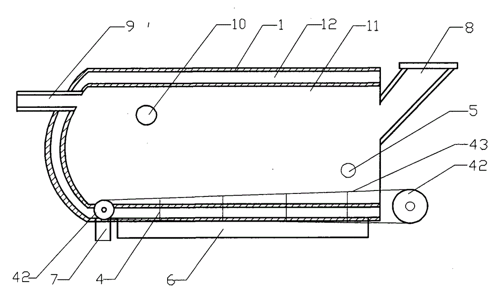
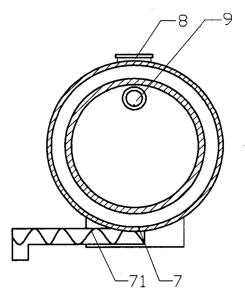
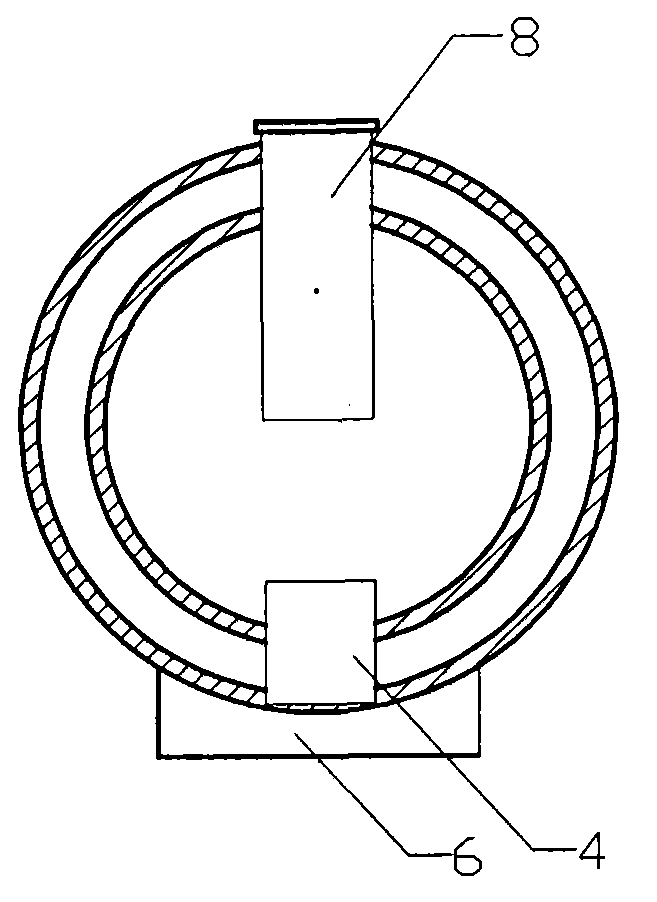
[0015] Such as figure 1 As shown, the biomass horizontal pyrolysis gasifier of the present invention has a structure comprising a horizontal furnace body 1, the left side is the front end of the furnace body, the right side is the rear end of the furnace body, the furnace body is a sandwich structure, and the interlayer inner cavity is a gasification chamber 11. In the middle of the interlayer is the air inlet chamber 12, the gas nozzle 9 is set at the front end of the furnace body, the feed port 8 is set at the rear end of the furnace body, the feed port and the gas nozzle are connected with the gasification chamber 11, and the side wall of the furnace body is opened The air inlet 5 communicates with the air inlet chamber 12 .

[0016] A feeding mechanism 4 is installed at the bottom of the furnace body, and its structure mainly includes guide wheel sets 41, 42 and recipr...


PUM


Abstract

The invention discloses a biomass horizontal pyrolysis gasifier. The structure of the biomass horizontal pyrolysis gasifier comprises a furnace body (1), a feed inlet (8), a gas nozzle (9), an air inlet (5) and an ash discharge opening (7). The feed inlet is arranged at the rear end of the furnace body. The furnace body (1) is a sandwich structure, wherein an inner cavity of the sandwich structure is a gasifying chamber (11), and the middle part of the sandwich structure is an air inlet chamber (12). The feed inlet (8) and the gas nozzle (9) are communicated with the gasifying chamber. The air inlet (5) is communicated with the air inlet chamber (12). The bottom of the furnace body is provided with a feed delivery mechanism (4). The gasifying chamber (11) and the air inlet chamber (12) are communicated with each other at the position of the feed delivery mechanism. According to the biomass horizontal pyrolysis gasifier, by introducing cold air into the air inlet of the sandwich structure, the furnace wall and a reciprocating grate are cooled, and heat-absorbed hot air also can flow upwards from the bottom of a feed layer through the reciprocating grate. By an up-to-bottom counter-burning mode, the feed layer will not be overlapped or mixed during operation of the reciprocating grate, multiple tower-type feed layers are formed to undergo continuous pyrogasification, and safe and stable operation can be carried out on the grate.

Description

technical field [0001] The invention relates to biomass energy equipment, more specifically to a horizontal biomass cracking gasifier. Background technique [0002] The high-temperature gasification chamber or furnace of common fixed-bed biomass gasification or semi-gasification furnace, common oxygen-limited combustion gasification from bottom to top, the upper part is fed with carbon layer covered with high-temperature combustion, the material layer is unstable, and wind And water vapor as a combustion support, the grate burns continuously in the high temperature area, easy to deform, crack and oxidize, the wind or water vapor rapidly reduces the temperature in the high temperature area, the carbon layer cannot be completely burned, affects the thermal efficiency, and reduces the calorific value of the gas. The vertical fixed bed furnace is limited by the inner diameter, which affects the gas production rate and gas production volume. Contents of the invention [0003] ...

Claims


Application Information

Patent Timeline
Patent Type & Authority Applications(China)
IPC IPC(8): C10J3/00
CPCC10J3/002C10J3/74C10J2200/15C10J2300/0916
Inventor 余小如
Owner JIANGMEN WANGDE CLEAN ENERGY
Learn More