Toilet bowl control system and method

A flush toilet and control system technology, applied in the field of flush toilets, can solve the problems that the sewage discharge efficiency cannot reach a stable and optimal state, the flow rate is low, and cannot be maintained, so as to improve the sewage discharge efficiency, and the sewage discharge efficiency is stable and good. washout effect

Inactive Publication Date: 2015-04-29
GLOBE UNION INDAL
View PDF7 Cites 7 Cited by
  • Summary
  • Abstract
  • Description
  • Claims
  • Application Information

AI Technical Summary

Problems solved by technology

[0004] However, it is well known that whether it is the traditional common pressure stabilizing valve, pressure reducing valve, or the automatic pressure reducing and stabilizing regulator disclosed in the above invention patent, the pressure can only be maintained within a certain range , that is, a relatively stable pressure, and cannot be maintained at a constant pressure. In this way, it is impossible to ensure that a fixed flow rate can be maintained each time the water is flushed, especially when the water source pressure is at a low or high pressure state, the flushing flow rate is even higher. There will be huge changes, such as the automatic decompression and voltage stabilization regulator of the above patent, after actual testing, its flow rate is low under low and high pressure conditions, and compared with the highest flow rate, it is about 20% lower
To sum up, since the current flow of the flush toilet cannot be maintained in a stable state, its sewage discharge performance has not been able to achieve a stable and optimal state.

Method used


Image

  • Toilet bowl control system and method
  • Toilet bowl control system and method
  • Toilet bowl control system and method

Examples


Embodiment Construction

[0048] The technical solutions of the present invention will be further described below in conjunction with the accompanying drawings and specific embodiments. It should be understood that the specific embodiments described here are only used to explain the present invention, not to limit the present invention.

[0049] The invention provides a control system and method for a flush toilet.

[0050] The present invention will be further described below in conjunction with the accompanying drawings and embodiments.

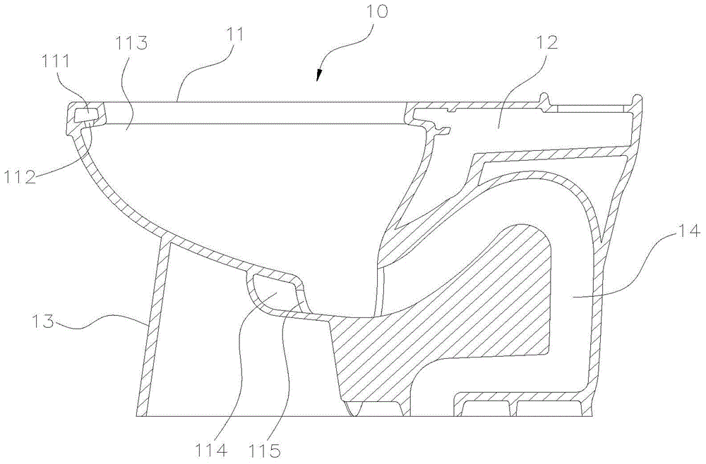
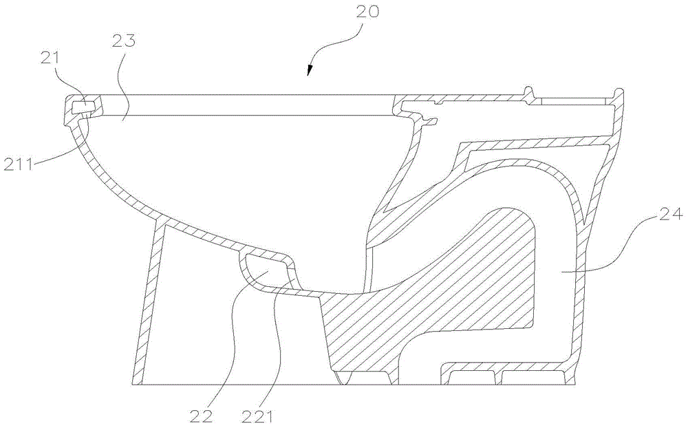
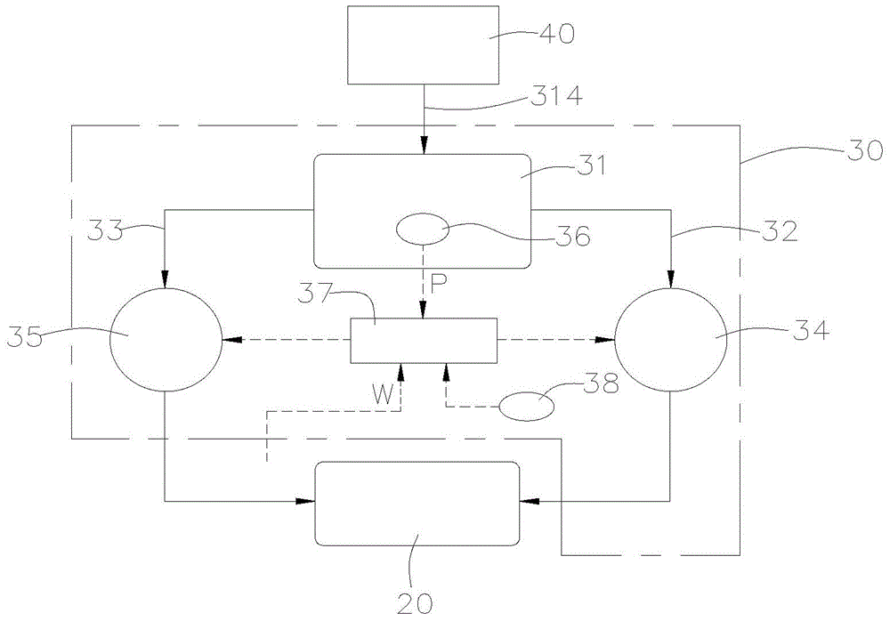
[0051] Such as figure 2 , 3 As shown, the present invention provides a preferred embodiment of a control system for a flush toilet. The toilet 20 has a water ring flush channel 21 and a nozzle flush channel 22; the control system 30 mainly includes a pressure reducing valve 31, a The water ring water supply pipeline 32, a jet outlet water supply pipeline 33, a water circle solenoid valve 34, a jet outlet solenoid valve 35, a water pressure sensor 36 and a contro...


PUM


Abstract

A system of controlling a flush toilet (20), which includes a first flushing channel (21) and a second flushing channel (22), and the system contains: a depressurizing valve (31) including an inlet (311) connecting with an inlet pipe fitting (314), a first outlet (312), and a second outlet (313); a first water-supply pipe fitting (32) employed to supply water from the first outlet (312) of the depressurizing valve (31) toward the first flushing channel (21) of the flush toilet (20); a second water-supply pipe fitting (33) applied to supply the water from the second outlet (313) of the depressurizing valve (31) toward the second flushing channel (22) of the flush toilet (20); a first solenoid valve (34) controlled to start and stop the first water-supply pipe fitting (32); a second solenoid valve (35) controlled to start and stop the second water-supply pipe fitting (33); a water pressure sensor (36) used to sense a water pressure in the depressurizing valve (31) and to transmit a pressure signal (P); a control unit (37) served to receive a flushing signal (W) started by a user and the pressure signal (P) from the water pressure sensor (36), such that after receiving the flushing signal (W), a starting and closing sequence and starting times of the first solenoid valve (34) and the second solenoid valve (35) are controlled based on the pressure signal (P).

Description

technical field [0001] The invention relates to the field of flush toilets, in particular to a control system and method for flush toilets. Background technique [0002] Such as figure 1 As shown, the currently known flush toilet includes a water tank (not shown in the figure) and a toilet body 10; the toilet body 10 has a cylinder part 11, a water inlet part 12, a support part 13 and a sewage pipe 14; wherein, the support part 13 is integrated It is connected to the front side of the cylinder body part 11 and the surrounding lower part. The top edge ring of the cylinder part 11 is provided with a water circle flushing channel 111 which communicates with the water inlet part 12, and the water circle flushing channel 111 is provided with a plurality of water circle water outlets 112, which can pass water from the water tank through the water inlet part. 12 and the water ring flushing channel 111 are guided and discharged into the cylinder part 11 for flushing the water ring...

Claims


Application Information

Patent Timeline
Patent Type & Authority Applications(China)
IPC IPC(8): E03D5/10E03D5/00
CPCE03D5/00E03D5/10E03D5/105E03D9/16E03D11/02E03D2201/30E03D1/142E03D5/02
Inventor 郭仲裕吴明佳陈炫综
Owner GLOBE UNION INDAL
Why Eureka
Try Eureka