
Improved clutch master cylinder assembly

A clutch master cylinder, an improved technology, applied in the field of auto parts, can solve problems such as easy oil leakage, poor oil compensation efficiency, complex cylinder structure, etc., achieve good sealing, prolong service life, and reduce complexity degree of effect

Active Publication Date: 2015-04-29
WUHU JUDA AUTO PARTS
View PDF8 Cites 4 Cited by
  • Summary
  • Abstract
  • Description
  • Claims
  • Application Information

AI Technical Summary

Problems solved by technology

[0002] The clutch is installed between the engine and the transmission. It is an assembly that is directly connected to the engine in the car drive train. Usually, the clutch is installed together with the crankshaft and flywheel of the engine. It is a component that cuts off and transmits power between the engine and the car drive train. The master cylinder is an important part of the clutch. The structural performance of the master cylinder directly affects the working efficiency of the brake. The application number is CN201210459421.1, which discloses an improved clutch master cylinder, including a cylinder body, a working chamber inside the cylinder body, and a push rod. And the oil inlet and outlet device arranged outside the cylinder body, the working chamber includes a U-shaped piston assembly and a push rod arranged inside the piston assembly and protruding to the outside of the cylinder body, and the piston assembly is sleeved with a cylinder end connector , the connecting head at the end of the cylinder body is threadedly connected with the inner wall of the cylinder body, the outer end of the connecting head at the end of the cylinder body is covered with a limit seat, and the push rod passes through the limit seat; with this structure, the clutch master cylinder has high strength, which is better than the original The plastic cylinder clutch is easy to cast and form, easy to repair, replace, install and disassemble. Low strength, poor dust resistance, and inconvenient oil intake, poor oil compensation efficiency)

Method used


Image

  • Improved clutch master cylinder assembly
  • Improved clutch master cylinder assembly

Examples


Embodiment Construction

[0013] In order to make the technical means, creative features, goals and effects achieved by the present invention easy to understand, the present invention will be further described below in conjunction with specific embodiments.

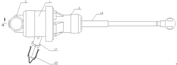
[0014] Such as figure 1 and figure 2 As shown, an improved clutch master cylinder assembly includes a cylinder body 1, an end connector 2, an oil outlet joint 3 and a piston assembly, and the oil outlet joint 3 is provided with a clip 26 and a stuffy cover 4, so The cylinder body 1 and the oil outlet joint 3 are integrally formed, the cylinder body 1 is threadedly connected with the end connector 2, and the connection between the cylinder body 1 and the end connector 2 is provided with an O-ring 5, and the end connection The head 2 is provided with an annular groove 6, the flange surface of the annular groove 6 is in the same plane as the end surface of the cylinder body 1, and the annular groove 3 is provided with a liner 7 and a corrugated el...


PUM


Abstract

The invention discloses an improved clutch master cylinder assembly and relates to the field of automobile parts. The improved clutch master cylinder assembly comprises a cylinder body, an end connector, an oil outlet connector and a piston assembly, wherein a clamp and a stifling cover are arranged on the oil outlet connector. The oil outlet connector and the cylinder body of the improved clutch master cylinder assembly are integrally formed, so that the strength of the master cylinder assembly is greatly improved, sealing performance is good, no oil leakage phenomenon does not occur, and meanwhile manufacturing difficulty is also reduced. A compensation hole and an oil inlet hole are respectively formed in a piston outer circle and the cylinder body, so that a small hole of diameter 0.7 is not needed to be machined, oil compensation is achieved, and meanwhile the complexity degree of the whole cylinder body is also reduced.

Description

technical field [0001] The invention relates to the field of auto parts, in particular to an improved clutch master cylinder assembly. Background technique [0002] The clutch is installed between the engine and the transmission. It is an assembly that is directly connected to the engine in the car drive train. Usually, the clutch is installed together with the crankshaft and flywheel of the engine. It is a component that cuts off and transmits power between the engine and the car drive train. The master cylinder is an important part of the clutch. The structural performance of the master cylinder directly affects the working efficiency of the brake. The application number is CN201210459421.1, which discloses an improved clutch master cylinder, including a cylinder body, a working chamber inside the cylinder body, and a push rod. And the oil inlet and outlet device arranged outside the cylinder body, the working chamber includes a U-shaped piston assembly and a push rod arra...

Claims


Application Information

Patent Timeline
Patent Type & Authority Applications(China)
IPC IPC(8): F16D25/12
Inventor 康伟铭汤宗兵
Owner WUHU JUDA AUTO PARTS
Learn More