water spray desuperheater

A technology of spraying water for temperature reduction and spraying holes, which is applied in the direction of superheating temperature control, steam superheating, steam generation, etc. It can solve the problems of low cooling water vaporization rate, water inflow of equipment, water hammer vibration, etc., and achieve the goal of overcoming water More steam and less, the effect of increasing the gasification rate

Inactive Publication Date: 2016-07-06
蒋娟
View PDF10 Cites 0 Cited by
  • Summary
  • Abstract
  • Description
  • Claims
  • Application Information

AI Technical Summary

Problems solved by technology

[0004] According to "Research on Desuperheater of Atomizing Nozzle" ("Power Plant Auxiliary Machinery" 1992 Issue 03, Zhang Shiyong of Dongfang Steam Turbine Factory), "Improvement of Reheating Steam Nozzle Desuperheater" ("Jilin Electric Power" 1996 Issue 06 Changshan Power Plant Ning Wenju, Wang Zhongcai), "Spray desuperheater throat structure" (CN203628624U), "350MW tangential combustion supercritical boiler reheater desuperheater" (CN202452476U), "Overall regulation and water spray According to relevant materials such as "Steam Desuperheater" (CN101907290A) and the technical scheme disclosed in the above-mentioned US invention patent application, there are two serious defects in the prior art of water spray desuperheater: one is that the cooling water vaporization rate is low— —When the cooling water leaves the nozzle, it enters into the superheated steam flow in the shape of a truncated cone, and instantly creates a situation of more water and less steam in the middle of the truncated cone. Therefore, more cooling water settles to a low place in the steam flow before it can absorb heat and vaporize. On the inner wall of the steam pipe, the steam pipe is discharged along the drain pipe; second, the cooling water that fails to absorb heat and vaporize is sprayed on the inner wall of the steam pipe, which will not only affect the service life of the steam pipe, but also easily cause water inflow and water hammer of the equipment Vibration and other serious accident hazards

Method used


Image

  • water spray desuperheater
  • water spray desuperheater
  • water spray desuperheater

Examples


Embodiment 1

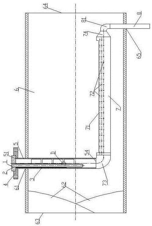
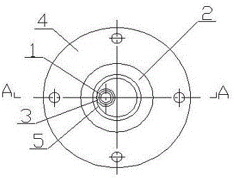
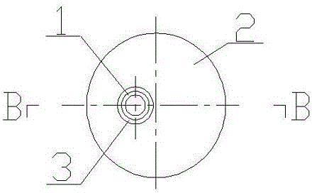
[0036] Such as Figure 14 with Figure 15As shown, a water spray desuperheater, said water spray desuperheater includes: nozzle 1, nozzle first flange 2, nozzle first atomizing sleeve 3, nozzle second flange 4, insertion pipe 5, Steam pipe section 6; the nozzle 1 is a stainless steel pipe, and its water inlet end is put into the eccentric hole 21 of the first flange 2 of the nozzle, and the seam is sealed and welded, and the other end of the nozzle 1 is sealed with a blocking plate Welding and sealing, at least one water spray hole 11 is arranged on the same side bus of the nozzle 1; the first flange 2 of the nozzle is installed in the round hole 41 of the second flange 4 of the nozzle, and the nozzle 1 Put into the steam pipe section 6 through the insertion pipe 5; the steam pipe section 6 has an inlet end 63 and an outlet end 64; a mixing plate 62 is arranged near the inlet end 63; the nozzle 1 is equipped with The first atomizing sleeve 3 of the nozzle, one end of which i...

Embodiment 2

[0038] Such as Figure 16 As shown, on the basis of Embodiment 1, at the port 54 where the insertion pipe 5 enters the middle part of the steam pipe section 6, the first elbow 73 is welded and connected to the evaporation pipe 7, and the joint is sealed and welded; The evaporation tube 7 is provided with an evaporation port 71 and a variable diameter joint 74; the secant of the evaporation port 71 provided on the evaporation tube 7 is located at 1 / 4 of the outer diameter of the evaporation tube 7; the aperture of the small end of the variable diameter joint 74 Equal to 3 / 4 of the diameter of the large end; the evaporation tube 7 is also provided with evaporation holes 72; the diameter of the evaporation holes 72 is 1 to 3 mm, and the spacing is 10 mm, and they are evenly distributed on the upper half of the evaporation tube 7 on the pipe wall.

Embodiment 3

[0040] Such as figure 1 As shown, on the basis of Embodiment 2, a second round hole 65 is set in the steam pipe section 6; the small diameter end of the reducing joint 74 of the evaporation pipe 7 is connected with the second elbow 81 and the drain pipe 8, The seams are sealed and welded; the drain pipe 8 extends out of the steam pipe section 6 through the second round hole 65 ; the seams of the drain pipe 8 and the second round hole 65 are sealed and welded.

[0041] Compared with the prior art, the advantage of Embodiment 1 is: the horizontal atomization grid is added, and the fan atomization nozzle provided on the first atomization sleeve of the nozzle guides the pressurized cooling water to impact on the atomization grid On the one hand, while increasing the atomization rate of the cooling water, it prevents the cooling water from spraying on the inner wall of the steam pipe, and the thickness ratio between the atomized group formed at the atomization grid and the superhe...


PUM


Abstract

The invention relates to a water spraying temperature reducer, which comprises a spray nozzle, a spray nozzle first flange, a spray nozzle first atomization sleeve, a spray nozzle second flange, an inserting pipe and a steam pipe section, wherein the spray nozzle first atomization sleeve is arranged on the spray nozzle, atomization spray openings with the same number as water spray holes are formed in the spray nozzle first atomization sleeve, the axial center line of each atomization spray opening is coincident with the axial center line of the corresponding water spray hole, on the basis of the water spraying temperature reducer, an atomization grid, an evaporation pipe and a drain pipe are additionally arranged, and the water spraying temperature reducer with different efficacies can be formed. The water spraying temperature reducer has the beneficial effects that the serious defects in the prior art are overcome, the cooling water vaporization rate is improved, and the safety of equipment and steam pipelines is improved.

Description

technical field [0001] The invention relates to the technical field of steam desuperheaters, in particular to a water spray desuperheater. Background technique [0002] The water spray desuperheater is a desuperheating device that sprays cooling water directly into the superheated steam flow passing through the steam pipe. The principle is: when the cooling water is mixed into the superheated steam, it will absorb heat from the superheated steam and turn it into steam, and the superheated steam will reduce the temperature from the original high temperature point to a certain low temperature point due to the heat release, so as to achieve superheating. The purpose of steam desuperheating. If the cooling water is sprayed into the superheated steam pipe as very fine water droplets or mist, the cooling water and the superheated steam are mixed more uniformly by the steam flow. The water spray desuperheater is characterized by simple structure, large temperature adjustment rang...

Claims


Application Information

Patent Timeline
Patent Type & Authority Patents(China)
IPC IPC(8): F22G5/12
Inventor 褚相武梁泳锋黎擎亮罗耀锋
Owner 蒋娟
Why Eureka
Try Eureka