Flue gas emission water cooling tower

A flue gas emission and cooling tower technology, applied in the field of cooling towers, can solve the problems of unreasonable structure of cooling towers and inability to meet emission standards, etc.

Active Publication Date: 2017-07-07
海南金航信诺节能科技有限公司 +1
View PDF5 Cites 0 Cited by
  • Summary
  • Abstract
  • Description
  • Claims
  • Application Information

AI Technical Summary

Problems solved by technology

However, the current cooling tower still has problems such as unreasonable structure and failure to meet the corresponding emission standards.

Method used


Image

  • Flue gas emission water cooling tower
  • Flue gas emission water cooling tower
  • Flue gas emission water cooling tower

Examples


Embodiment Construction

[0018] The following will clearly and completely describe the technical solutions in the embodiments of the present invention with reference to the accompanying drawings in the embodiments of the present invention. Obviously, the described embodiments are only some of the embodiments of the present invention, not all of them. Based on the embodiments of the present invention, all other embodiments obtained by persons of ordinary skill in the art without making creative efforts belong to the protection scope of the present invention.

[0019] In order to enable those skilled in the art to better understand the solution of the present invention, the present invention will be further described in detail below in conjunction with the accompanying drawings and specific embodiments.

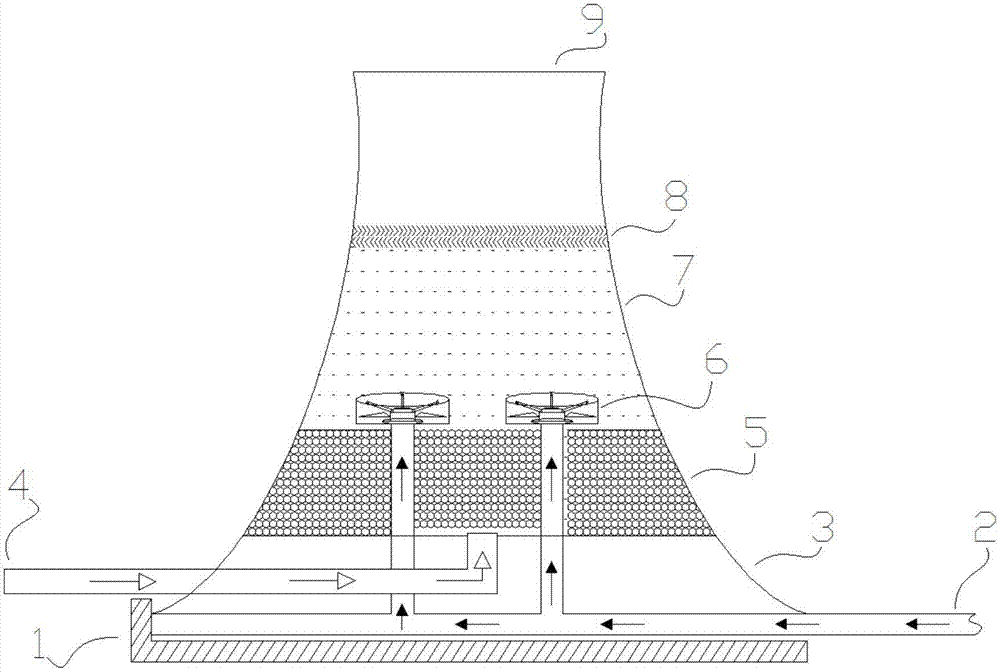
[0020] Please refer to figure 1 , figure 1 It is a structural schematic diagram of a flue gas discharge water cooling tower provided by an embodiment of the present invention.

[0021] A flue gas dis...


PUM

PropertyMeasurementUnit
thicknessaaaaaaaaaa

Abstract

The invention discloses a flue gas emission water cooling tower comprising a side wall with a hyperbolic longitudinal section and internally provided with a hollow part; a cooling water pool which is located at the bottom of the tower and above which a hot water inlet and a smoke pipe are arranged in turn; a heat dissipation layer, an atomization device and a water catchment device which are arranged in the hollow part in turn from bottom to top, and an atomization layer is formed between the atomization device and the water catchment device; an air inlet is formed between the hot water inlet and the heat dissipation layer; vapor discharged from the hot water inlet and waste smoke discharged from the smoke pipe are mixed and atomized in the atomization layer after passing through the atomization device, and discharged through an outlet after shifting to the water catchment device upward. The flue gas emission cooling tower has the advantages of rational structure and emission compliance, and meets the environmental protection requirements.

Description

technical field [0001] The invention relates to the technical field of cooling towers, in particular to a flue gas discharge water cooling tower. Background technique [0002] As the problem of environmental pollution becomes more and more serious, the issue of environmental protection has also received more and more attention from countries all over the world. The pollution of sulfide in air pollution is one of the important issues facing the world today, and it is an important source of sulfide emissions. [0003] The cooling tower in the prior art uses the cooling tower to discharge flue gas. The cooling tower not only has the original heat dissipation function, but also replaces the chimney to discharge the clean flue gas after desulfurization. However, the current cooling tower still has problems such as unreasonable structure and failure to meet the corresponding emission standards. Contents of the invention [0004] The object of the present invention is to provid...

Claims


Application Information

Patent Timeline
Patent Type & Authority Applications(China)
IPC IPC(8): F28C1/00F28F25/06B01D53/78B01D53/50B01D53/56B01D47/06
CPCB01D47/06B01D53/50B01D53/56B01D53/78B01D2258/0283F28C1/00F28F25/06
Inventor 史仲文
Owner 海南金航信诺节能科技有限公司
Why Eureka
Try Eureka