Gas Turbine Combustor Head Structure and Combustion Organization Method

A gas turbine and combustor technology, applied in the direction of combustion methods, combustors, continuous combustors, etc., can solve the problems of flat rise in nitrogen oxide emission levels, failure to meet emission standards, limited potential, etc., to reduce the possibility, Save cooling structure design and save cooling area

Active Publication Date: 2018-03-23
CHINA UNITED GAS TURBINE TECH CO LTD
View PDF5 Cites 0 Cited by
  • Summary
  • Abstract
  • Description
  • Claims
  • Application Information

AI Technical Summary

Problems solved by technology

Comparing the latest combustion chamber products in the 1990s and the present in the world, it can be seen that the average outlet temperature has increased by about 200°C. Although the combustion chamber has undergone a series of optimizations and improvements, the emission level of nitrogen oxides has remained the same or even slightly increased. This shows that the current combustor design structure has limited potential when targeting future higher parameter combustors, and faces the risk of not meeting emission standards

Method used


Image

  • Gas Turbine Combustor Head Structure and Combustion Organization Method
  • Gas Turbine Combustor Head Structure and Combustion Organization Method
  • Gas Turbine Combustor Head Structure and Combustion Organization Method

Examples


Embodiment 1

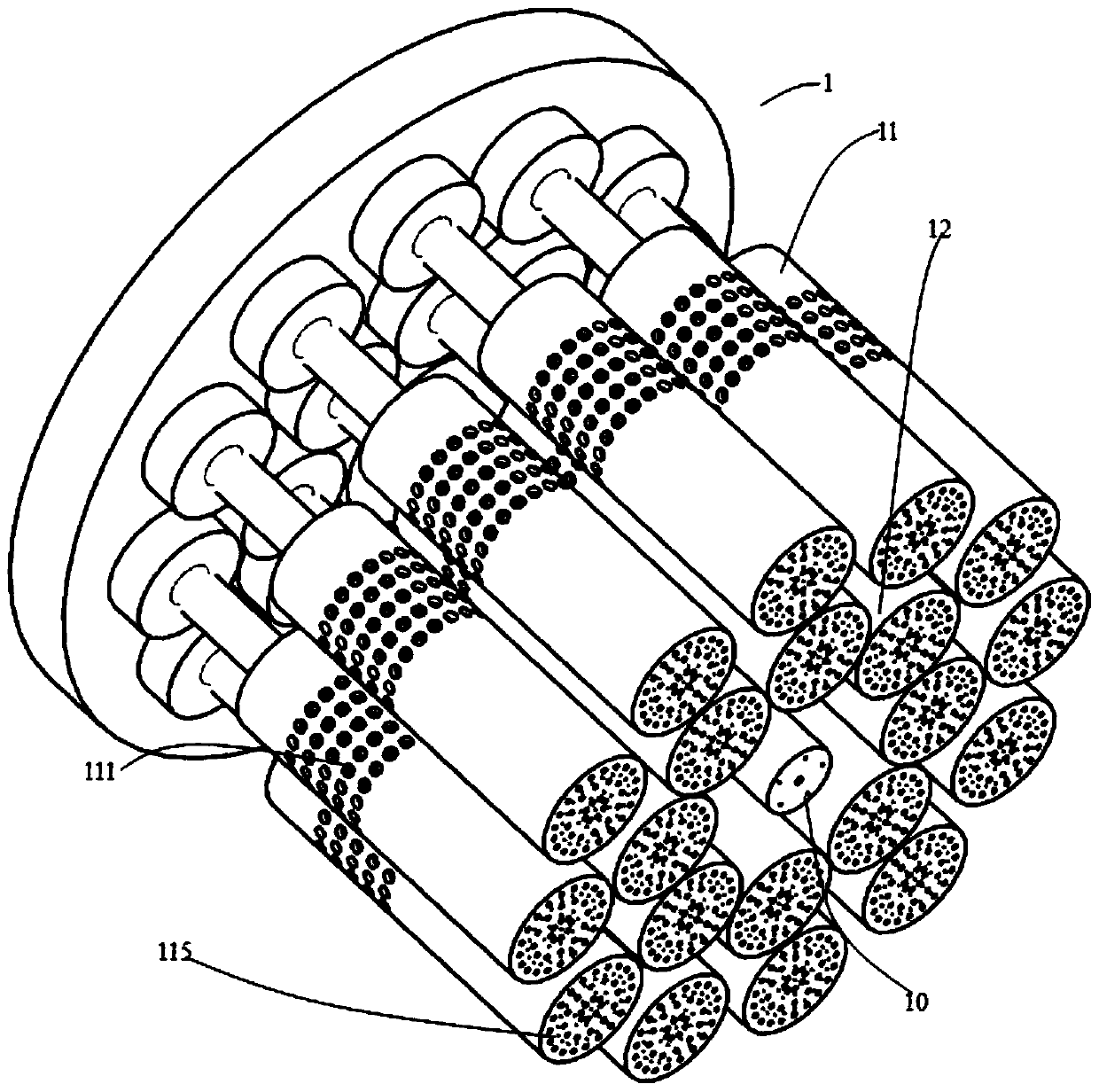
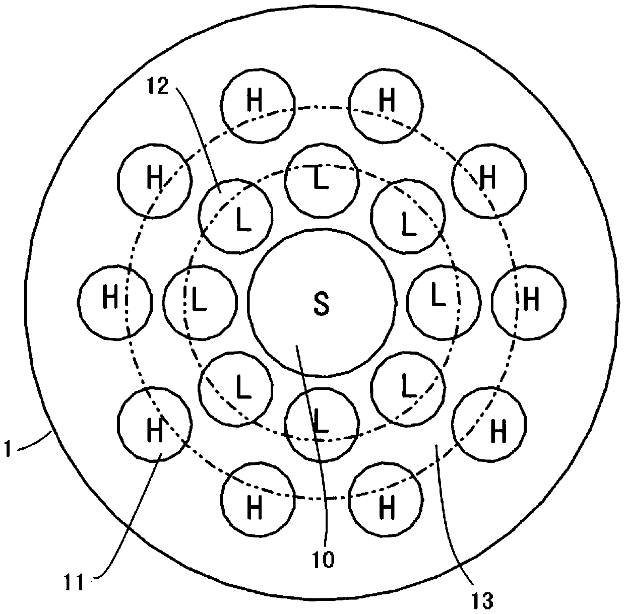
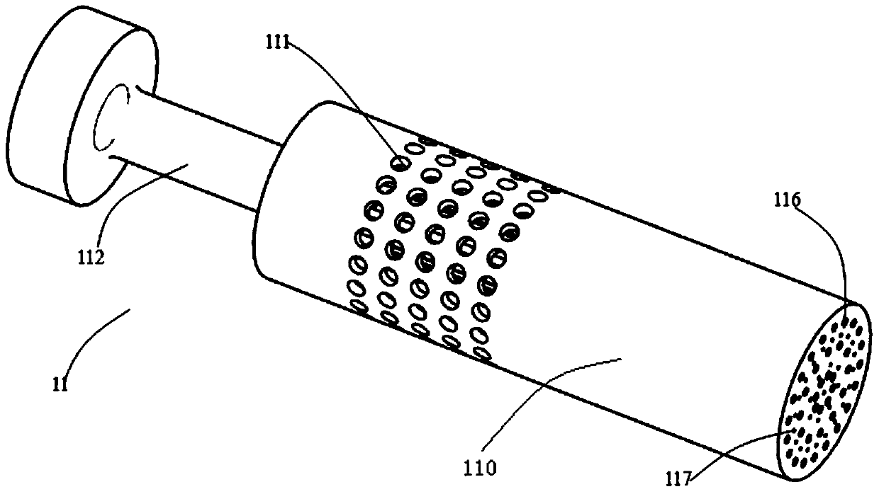
[0030] refer to Figures 1 to 6 As shown, the gas turbine combustor head structure of the present invention includes a head end plate 1 , a central swirl nozzle module 10 , a plurality of high-speed jet nozzle modules 11 and a plurality of low-speed jet nozzle modules 12 . The central swirl nozzle module 10 is installed on the head end plate 1 and is located at the center of the head end plate 1 . A plurality of high-speed jet nozzle modules 11 and a plurality of low-speed jet nozzle modules 12 are also mounted on the head end plate 1 and arranged around the central swirl nozzle module 10 to form an inner nozzle circle and an outer nozzle circle. The head end plate 1 is provided with a plurality of fuel intake passages for supplying fuel to the central swirl nozzle module 10 , the high-speed jet nozzle module 11 and the low-speed jet nozzle module 12 . Wherein, the average equivalent ratio of the high-speed jet nozzle module 11 is smaller than the average equivalent ratio of ...

Embodiment 2

[0040] The head structure of the gas turbine combustor in this embodiment includes a head end plate 1 , a central swirl nozzle module 10 , a plurality of high-speed jet nozzle modules 11 and a plurality of low-speed jet nozzle modules 12 . The central swirl nozzle module 10 is installed on the head end plate 1 and is located at the center of the head end plate 1 . A plurality of high-speed jet nozzle modules 11 and a plurality of low-speed jet nozzle modules 12 are also mounted on the head end plate 1 and arranged around the central swirl nozzle module 10 to form an inner nozzle circle and an outer nozzle circle. The head end plate 1 is provided with a plurality of fuel intake passages for supplying fuel to the central swirl nozzle module 10 , the high-speed jet nozzle module 11 and the low-speed jet nozzle module 12 . Wherein, the central swirl nozzle module 10, the high-speed jet nozzle module 11, and the low-speed swirl nozzle module 12 are all the same as in Embodiment 1, ...


PUM


Abstract

The invention relates to the technical field of gas turbine combustors, and discloses a head structure of a gas turbine combustor, including a head end plate, a central swirl nozzle module, a plurality of high-speed jet nozzle modules and a plurality of low-speed jet nozzle modules. The flow nozzle module is installed on the head end plate; a plurality of the high-speed jet nozzle modules and a plurality of the low-speed jet nozzle modules are installed around the center swirl nozzle module, forming an inner nozzle ring and an outer nozzle ring. Nozzle ring. The invention adopts a plurality of high-speed jet nozzles and low-speed jet nozzle modules to form a distributed flame that is continuously "extinguished and reburned" locally, reduces the peak temperature of the flame at a higher average outlet temperature, and suppresses the formation of nitrogen oxides. At the same time, a combustion organization method of a gas turbine combustor is also provided.

Description

technical field [0001] The invention relates to the technical field of gas turbine combustors, in particular to a gas turbine combustor head structure and a combustion organization method thereof. Background technique [0002] For industrial heavy-duty gas turbines, the development goals for decades have always been higher average temperature of the combustion chamber outlet (standardized gas turbine technical level) and lower pollutant emissions; the above technical indicators are closely related to the combustion chamber and contradict each other, higher The average temperature at the outlet of the combustion chamber means that more fuel participates in the combustion process, and the average temperature in the combustion chamber is higher. Nitrogen oxides, which are the main pollutants in the combustion chamber, are closely related to the thermal process inside the combustion chamber. The basic function of the gas turbine combustor is to convert the chemical energy in the...

Claims


Application Information

Patent Timeline
Patent Type & Authority Patents(China)
IPC IPC(8): F23R3/42
Inventor 方子文吕煊李珊珊张永良陈伟
Owner CHINA UNITED GAS TURBINE TECH CO LTD
Why Eureka
Try Eureka