Ground smoke channel air returning furnace

A technology of return air furnace and floor smoke, which is used in household furnaces/stoves, lighting and heating equipment, solid heating fuels, etc., can solve problems such as large use space, flue burns, occupation, etc. Clean and beautiful, the effect of increasing the length

Inactive Publication Date: 2015-04-29
湖北鑫星节能炉具有限公司
View PDF0 Cites 1 Cited by
  • Summary
  • Abstract
  • Description
  • Claims
  • Application Information

AI Technical Summary

Problems solved by technology

[0002] The flues of existing stoves are all attached to the stove, and the smoke flows through the flue and is directly discharged outside. The horizontal flue also occupies a large space for use. The flue on the furnace body is prone to burns

Method used


Image

  • Ground smoke channel air returning furnace

Examples


Embodiment 1

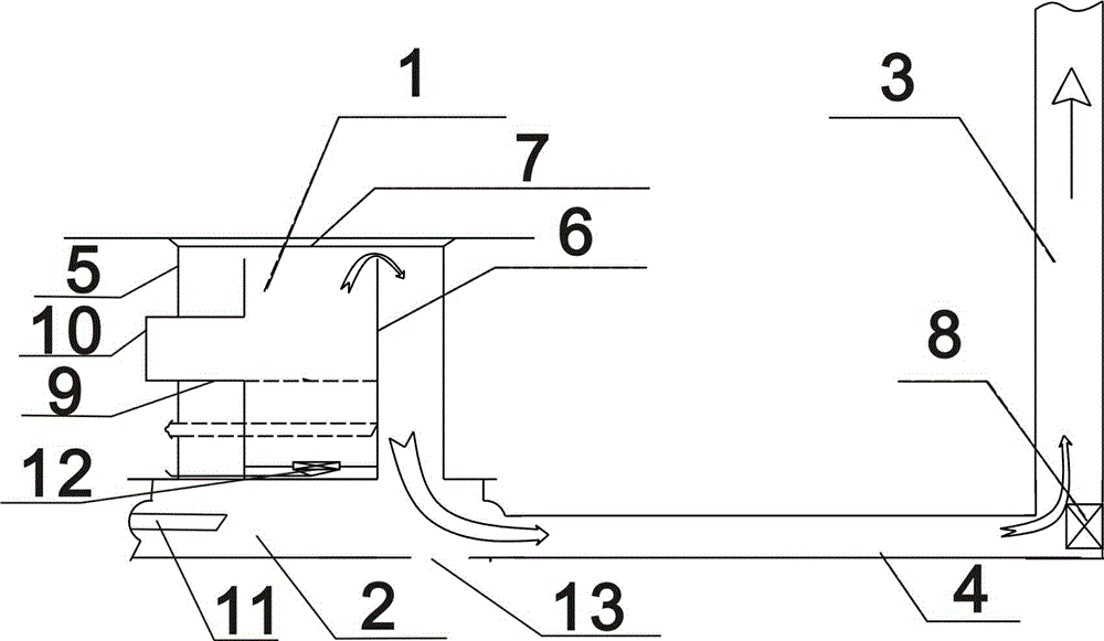
[0014] A ground flue return air furnace, including a furnace body 1, a foot box 2, and a smoke pipe, wherein the smoke pipe includes a straight smoke pipe 3 and a horizontal smoke pipe 4, wherein the foot box 2 and the furnace body 1 are connected through an interlayer tempering channel , the straight smoke pipe 3 is connected with the foot box 2 through the horizontal smoke pipe 4. At the corner of the straight smoke pipe 3 and the horizontal smoke pipe 4, an ash removal and ignition device 8 is arranged. The horizontal smoke pipe 4 is arranged close to the ground or buried underground, and its shape is cylindrical, semi-cylindrical or cube-like.

[0015] The tempering passage is an interlayer formed by the outer cylinder 5 and the inner tank 6 .

[0016] A fire-proof cover 7 is arranged on the furnace surface of the furnace body 1 .

[0017] The bottom plate of the foot box 2 is provided with a dust removal port 13 .

[0018] The inner tank 6 is also provided with a furna...


PUM


Abstract

The invention relates to a ground smoke channel air returning furnace. A foot box is connected with a furnace body through an interlayer backfiring channel, and a straight smoke pipe is connected with the foot box through a horizontal smoke pipe. According to the device, a smoke channel is tightly attached on the ground or a wall surface or is buried underground, the indoor space can be used to the maximum degree, and a smoke flow passes through a foot box, a horizontal smoke channel and then a straight smoke channel to be discharged out of a room. The smoke heat exchange area is expanded, and the heat efficiency is improved.

Description

technical field [0001] The invention relates to a ground flue air return furnace, in particular to a device for discharging smoke from a foot box through a horizontal flue and then through a straight flue to the outside. Background technique [0002] The flues of existing stoves are all attached to the stove, and the smoke flows through the flue and is directly discharged outside. The horizontal flue also occupies a large space for use. The flue on the furnace body is prone to burns. Contents of the invention [0003] The purpose of the present invention is to provide a device for the ground flue return air furnace, the device is installed with the flue close to the ground or wall or buried underground, which can maximize the use of indoor space and increase the heat exchange area of ​​the flue. Ground flue return air furnace with improved thermal efficiency. [0004] The present invention achieves the above object like this: [0005] A ground flue return air furnace, i...

Claims


Application Information

Patent Timeline
Patent Type & Authority Applications(China)
IPC IPC(8): F24B1/189
Inventor 高洪亮
Owner 湖北鑫星节能炉具有限公司
Why Eureka
Try Eureka