Thermal siphon oil cooling system
An oil cooling system and thermosiphon technology, applied in refrigerators, refrigeration components, refrigeration and liquefaction, etc., can solve the problems of increasing the complexity of the structure of the thermosiphon liquid receiver 1, increasing the process complexity of the thermosiphon oil cooler, and excessive loss To solve problems such as coldness, achieve the effect of simple thermosiphon oil cooling process, simple structure, and effective utilization
- Summary
- Abstract
- Description
- Claims
- Application Information
AI Technical Summary
Problems solved by technology
Method used
Image
Examples
Embodiment approach
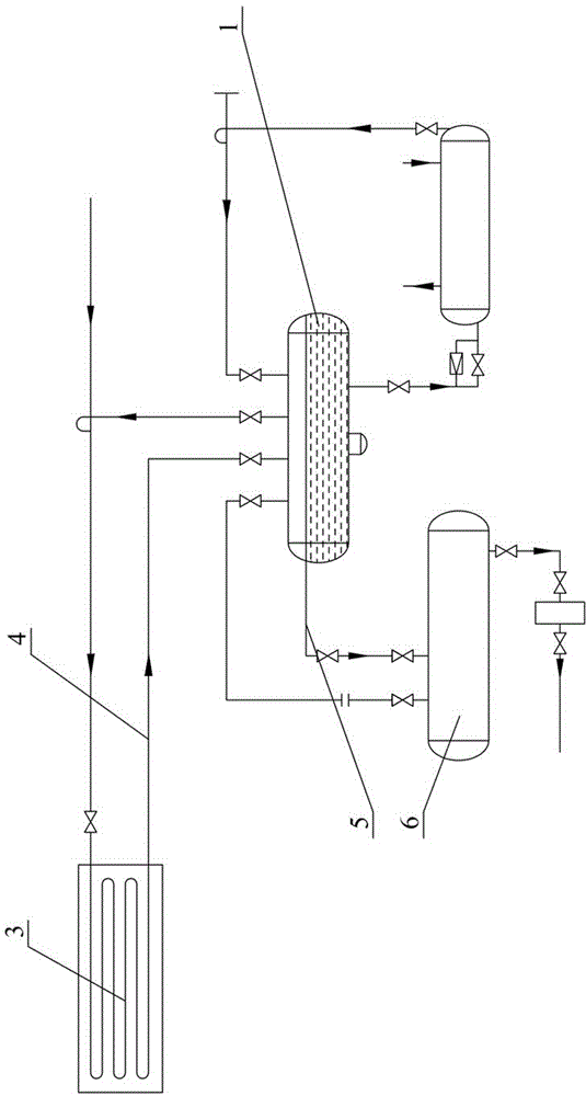
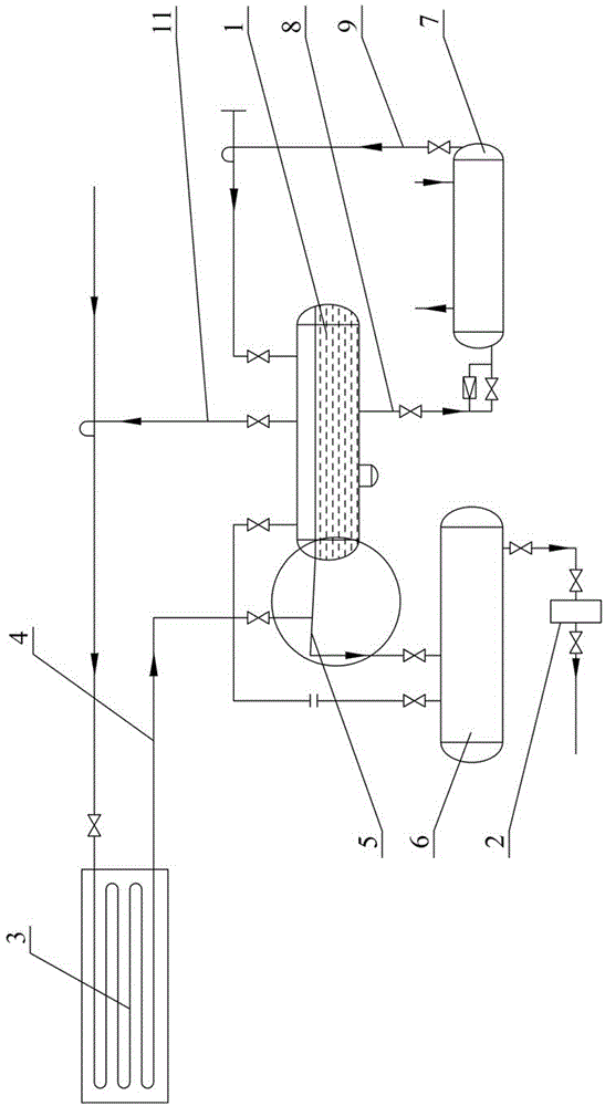
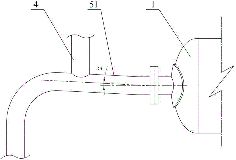
[0028] figure 2 and image 3 The first embodiment of the thermosiphon oil cooling system of the present invention is shown, including a thermosiphon liquid reservoir 1, a return gas pipeline 11, a regulating station 2, a condenser 3, a condenser liquid outlet pipe 4, and a thermosiphon liquid reservoir The overflow pipe 5, the high-pressure liquid reservoir 6, the thermosiphon oil cooler 7, the liquid outlet pipe 8 of the thermosiphon liquid reservoir, the air return pipe 9 of the oil cooler, and the high-pressure liquid reservoir 6 communicate with the regulating station 2 through pipelines. The thermosiphon liquid reservoir 1 is provided with an air return port, an overflow port, an air outlet and a liquid outlet, wherein the air return port is connected with the thermosiphon oil cooler 7 through the oil cooler return air pipe 9, and the overflow port and the high pressure The liquid reservoir 6 is communicated with the overflow pipe 5 of the thermosiphon liquid reservoir,...
Embodiment 2
[0038] Figure 4The second embodiment of the thermosiphon oil cooling system of the present invention is shown. The difference from the first embodiment is that the heat insulation pipe section 51 includes a first reducing pipe 511, a horizontal pipe 512 and a second reducing pipe 513, The horizontal pipe 512 connects the large end of the first variable diameter tube 511 and the large end of the second variable diameter tube 513, the small end of the first variable diameter tube 511 is close to the overflow port of the thermosiphon liquid reservoir 1, and the second variable diameter tube The small head end of the pipe 513 is close to the high-pressure liquid reservoir 6 , and the outlet pipe 4 of the condenser is connected to the horizontal pipe 512 and is close to the second reducing pipe 513 . The first reducing tube 511 and the second reducing tube 513 may be concentric or eccentric reducing tubes. The lowest point of the inner wall of the small head end of the second var...
Embodiment 3
[0041] Figure 5 The third embodiment of the thermosiphon oil cooling system of the present invention is shown. The difference from the second embodiment is that the heat insulation pipe section 51 includes a second reducing pipe 513 and a horizontal pipe 512, and one end of the horizontal pipe 512 is connected to the heat The overflow port of the siphon liquid reservoir 1 is connected, and the other end is connected with the big end of the second variable diameter pipe 513, the small end of the second variable diameter pipe 513 is close to the high pressure liquid reservoir 6, and the condenser liquid outlet pipe 4 is connected to the horizontal The tube 512 is connected and is close to the second reducing tube 513 .
PUM
 Abstract
Description
Claims
Application Information
 - R&D
- Intellectual Property
- Life Sciences
- Materials
- Tech Scout
- Unparalleled Data Quality
- Higher Quality Content
- 60% Fewer Hallucinations
Browse by: Latest US Patents, China's latest patents, Technical Efficacy Thesaurus, Application Domain, Technology Topic, Popular Technical Reports.
© 2025 PatSnap. All rights reserved.Legal|Privacy policy|Modern Slavery Act Transparency Statement|Sitemap|About US| Contact US: help@patsnap.com


