Serrated air outlet air knife structure for glass cleaning/drying machine

A glass cleaning and air outlet technology, applied in dryers, drying gas arrangement, drying, etc., can solve the problems of affecting the drying effect, incorrect air outlet angle, and increased energy consumption of air knives

Inactive Publication Date: 2015-04-29
CHANGZHOU SOGLASS MACHINERY
View PDF1 Cites 3 Cited by
  • Summary
  • Abstract
  • Description
  • Claims
  • Application Information

AI Technical Summary

Problems solved by technology

Increasing the air knife will inevitably increase energy consumption
[0005] Second, because the glass transmission of the glass washing and drying machine adopts the clamping transmission mode of the upper and lower rubber rollers, the oblique air knife 2 of the traditional equipment is inclined, and forms a certain angle with the direction of the running glass, that is, forms a certain angle with the transmission roller. , the inclined air knife 2 of this structure must cut the corresponding part of the rubber roller 3 into two sections to meet the glass operation, but this will cause the installation of the rubber roller 3 to be inconvenient, and it will easily lead to incorrect angles of the air outlet, which will affect the air-drying effect , and cause high maintenance frequency and low working stability. At the same time, the setting of the inclined air knife 2 greatly increases the length of the overall equipment, so this form greatly increases the manufacturing cost of the equipment. In addition, the truncation of the rubber roller 3 is also Increased the limitations of the use of equipment, small pieces of glass can not meet the transmission
[0006] Technical personnel in the industry know that traditional glass washing and drying machines consume a lot of energy and are inconvenient to manufacture and maintain. In order to solve the above-mentioned deficiencies in the prior art, Chinese patent 201220366108.9 is an air knife structure for glass washing and drying machines, such as figure 2 As shown, the rubber roller 3 is installed on the frame through the bearings at both ends, and the air knife body 4 is installed between two adjacent rubber rollers 3, and a plurality of guiding guides are provided on the top surface of the air knife body 4 along the length direction. The air outlet 5, and all the air guide outlets 5 are parallel to each other; the air knife structure with this inclined air outlet structure is used to replace the traditional inclined air knife 2, and the inclined air knife body 4 can be installed on two parallel rubber rollers 3 Between, there is no need to destroy the integrity of the rubber roller 3, shorten the overall length of the air knife body 4, reduce the footprint of the equipment, and improve the stability of the rubber roller 3 during work, because the length of each air guide outlet 5 of this structure Shorter, it is easy to ensure the consistency of its length and width during processing, and effectively improve the uniformity of the air volume of each air guide outlet 5. However, because the air guide outlets 5 are arranged in parallel in this way, the first air guide outlet 5 blows After drying the water on the glass surface in the area, it will be re-covered by the water blown away by the second air guide outlet 5. Practice has proved that it cannot replace the inclined air knife 2, and cannot completely dry the glass at one time. The actual drying effect is not ideal. At present, this scheme has been abandoned by industry personnel

Method used


Image

  • Serrated air outlet air knife structure for glass cleaning/drying machine
  • Serrated air outlet air knife structure for glass cleaning/drying machine
  • Serrated air outlet air knife structure for glass cleaning/drying machine

Examples


Embodiment 1

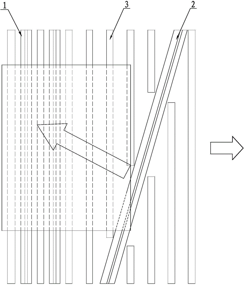
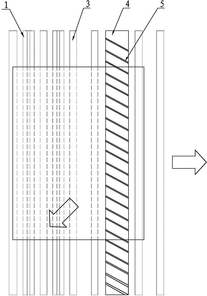
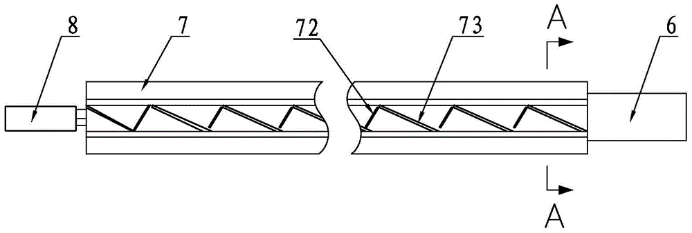
[0027] A sawtooth air outlet air knife structure for a glass washing and drying machine, comprising an air inlet pipe 6, a sawtooth air outlet air knife body 7 and a fixed shaft 8 at the tail of the air knife, an air inlet pipe 6, a sawtooth air outlet air knife body 7 and a wind The fixed shaft 8 at the tail of the knife is coaxially connected, and the air inlet pipe 6 is fixedly installed on the air inlet end of the sawtooth air outlet air knife body 7, and communicates with the inner chamber 71 of the sawtooth air outlet air knife body 7, and the fixed shaft at the end of the air knife 8 is fixedly installed on the corresponding end of the air inlet end of the zigzag air outlet air knife body 7, and the zigzag air outlet air knife body 7 is fixedly installed between two adjacent rubber rollers 3 and parallel to the rubber rollers 3, and the zigzag air outlet air The top surface of the cutter body 7 is inclined along the length extension direction and has a plurality of zigza...


PUM


Abstract

The invention provides a serrated air outlet air knife structure for a glass cleaning / drying machine. A serrated air outlet air knife body is mounted between two adjacent rubber rollers and parallel to the rubber rollers; a serrated air outlet formed by connecting inclined air guide outlets and straight air guide outlets end to end is formed in the top surface of the serrated air outlet air knife body in the length direction, all the inclined air guide outlets are parallel to each other, and an included angle for forcing water to go forwards is formed between the air outlet direction of the inclined air guide outlets and a glass moving direction. When glass passes through the air knife, air blown out by the inclined air guide outlets is capable of blowing water on the surface of the glass forwards; besides, air out of the straight air guide outlets forms an air wall within the acting region thereof to prevent the water blown out to cover the acting region of the adjacent inclined air guide outlet; as a result, each serrated air blowing opening is capable of blowing away water in the local region, and the water attached on the surface of the glass can be blown away once; meanwhile, the length of the machine can be greatly reduced, more than 30% of energy can be saved, and the serrated air outlet air knife structure is an efficient and energy-saving air-drying device.

Description

Technical field: [0001] The invention relates to the technical field of glass washing and drying machines, in particular to an air knife structure for glass washing and drying. Background technique: [0002] The air knife body used in the glass cleaning and drying machine is that after the glass is cleaned by a brush, the wind pressure is generated by the fan, and then the wind is guided out through the air guide port, forming a certain angle with the glass surface. When the glass with water on the surface passes through the air port , a device that uses wind energy to clean water stains on the glass surface. In terms of glass cold end processing equipment, glass washing and drying machine is a kind of equipment with relatively high energy consumption, and its main energy consumption is concentrated on the air knife for drying glass, for example: 2000mm wide glass washing and drying is used for glass washing and drying The air knife energy consumption of the machine can rea...

Claims


Application Information

Patent Timeline
Patent Type & Authority Applications(China)
IPC IPC(8): F26B21/00
Inventor 林卫华
Owner CHANGZHOU SOGLASS MACHINERY
Why Eureka
Try Eureka