
Position measuring method for pole-mounted transformer

A pole-mounted transformer and measurement method technology, applied to measuring devices, mechanical measuring devices, instruments, etc., can solve problems such as inaccurate measurement results, high risk factors, and unchanged use and operation

Inactive Publication Date: 2015-04-29
XIAN UNIV OF SCI & TECH
View PDF4 Cites 2 Cited by
  • Summary
  • Abstract
  • Description
  • Claims
  • Application Information

AI Technical Summary

Problems solved by technology

[0004] The technical problem to be solved by the present invention is to provide a method for measuring the position of a pole-mounted transformer in view of the deficiencies in the above-mentioned prior art. The existing methods for measuring the position of transformers on poles have problems such as constant operation, high risk factor, and inaccurate measurement results.

Method used


Image

  • Position measuring method for pole-mounted transformer
  • Position measuring method for pole-mounted transformer
  • Position measuring method for pole-mounted transformer

Examples


Embodiment 1

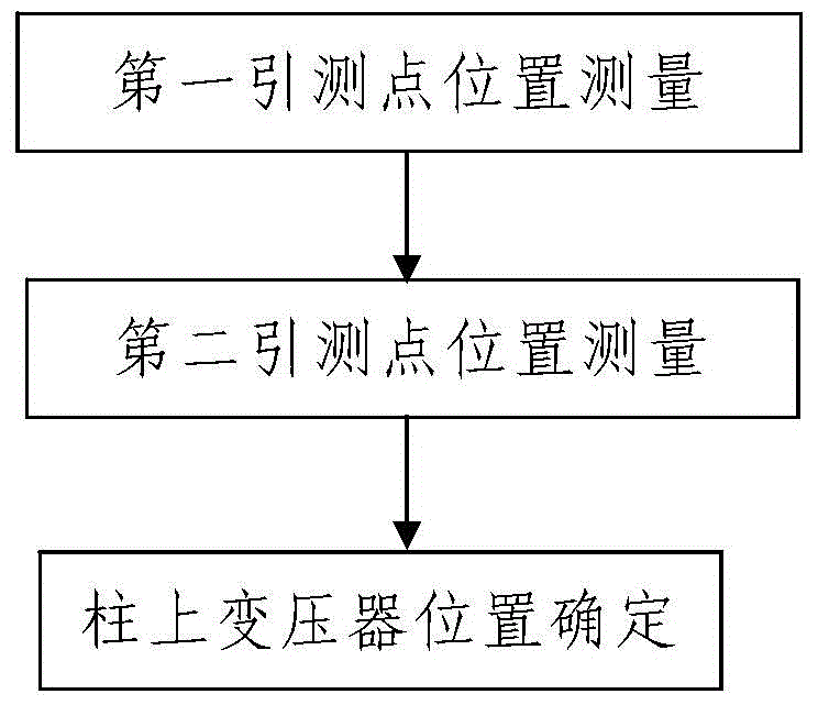
[0049] Such as figure 1 A method for measuring the position of a pole-mounted transformer includes the following steps:

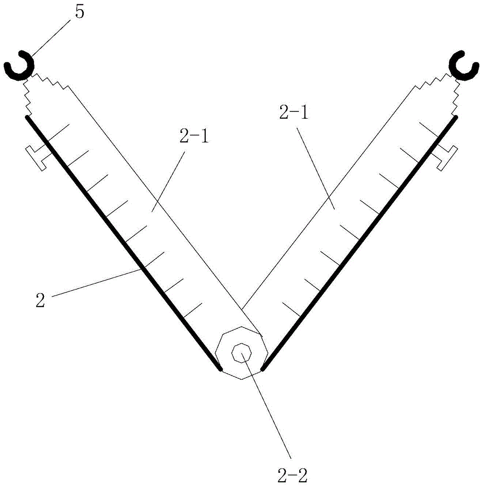
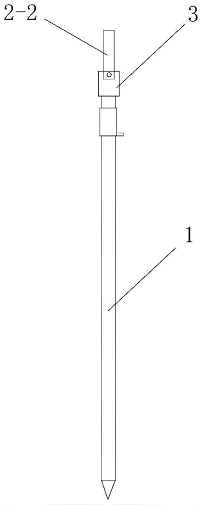
[0050] Step 1. Measurement of the position of the first lead measuring point: use the auxiliary measuring device to measure the position of the first lead measuring point below the side of the transformer on the measured column; figure 2 , image 3 As shown, the auxiliary measuring device includes a V-shaped measuring ruler 2 and a centering rod 1 installed under the rear part of the V-shaped measuring ruler 2 and capable of swinging back and forth on a vertical plane. The V-shaped measuring ruler 2 includes left and right Two measuring rulers 2-1, the structure and size of the two measuring rulers 2-1 are the same and the two are symmetrically arranged left and right, and the rear ends of the two measuring rulers 2-1 are connected in a hinged manner And the rear ends of the two are installed on the hinge shaft 2-2, and the rear ends of the two measuring...

Embodiment 2

[0088] In this embodiment, different from Embodiment 1, the V-shaped measuring ruler 2 described in step 201 and the V-shaped measuring ruler 2 described in step 101 are all located on the same side of the transformer on the measured column; The second testing point and the first testing point in step 102 are located on the same side of the point C to be tested, and L B > L A . In this way, the actual measurement is very simple. After the first point to be measured is determined in step 1, the V-shaped measuring ruler 2 used in step 1 is stretched horizontally to the outside, and the second lead measurement point is determined accordingly.

[0089]In this embodiment, when determining the position of the transformer on the pole in step 3, the two-dimensional coordinates (x A ,y A ) and the two-dimensional coordinates (x B ,y B ), and according to the formula Δx = x ...


PUM


Abstract

The invention discloses a position measuring method for a pole-mounted transformer. The position measuring method comprises the steps that 1, a first pilot testing point position is measured, wherein an auxiliary measuring device is adopted for measuring the first pilot testing point position below one side of the pole-mounted transformer, the auxiliary measuring device is installed, the first pilot testing point position is determined and measured, and the distance from a first pilot testing point to a point to be measured is determined; the auxiliary measuring device comprises V-shaped measuring scales and centering rods installed at the bottoms of the V-shaped measuring scales, and the two measuring scales are telescopic rulers; 2, a second pilot testing point position is measured, wherein the auxiliary measuring device is installed, the second pilot testing point position is determined, the second pilot testing point position is measured, and the distance from a second pilot testing point to the point to be measured is determined; 3, the position of the pole-mounted transformer is determined. According to the method, the steps are simple, design is reasonable, operation is simple, safe and reliable, the measurement result is accurate, and the problems that use and operation are not changed, the danger coefficient is high and the measurement result is inaccurate when an existing pole-mounted transformer position measuring method is used can be solved.

Description

technical field [0001] The invention relates to a method for measuring the position of electric equipment, in particular to a method for measuring the position of a pole-mounted transformer. Background technique [0002] During the general survey of power equipment, it is required to monitor the substation equipment of the power supply company and determine the specific location of each substation equipment. The above-mentioned substation equipment mainly includes "substation room", "distribution box" and "column transformer" three parts. Among them, the pole-mounted transformer (also known as "pole-mounted transformer") refers to an outdoor distribution transformer installed on a pole. The transformer on the pole is installed outdoors, and the installation height is generally about 2.5m higher than the ground. However, in actual installation, due to the limitation of the terrain of the specific installation location and the surrounding environmental factors, the installati...

Claims


Application Information

Patent Timeline
IPC IPC(8): G01B5/00
Inventor 朱庆伟
Owner XIAN UNIV OF SCI & TECH
Learn More