
Planar Parallel 3D Force Sensor

A three-dimensional force and sensor technology, used in instruments, force/torque/work measuring instruments, measuring devices, etc., can solve the problem of not being able to measure the radial impact load of the bearing at the same time, not being able to measure the friction torque of the bearing at the same time, and the inability to measure the torque, etc. problem, to achieve the effect of simple structure, low cost and avoiding equipment loss

Active Publication Date: 2017-01-25
YANSHAN UNIV
View PDF9 Cites 0 Cited by
  • Summary
  • Abstract
  • Description
  • Claims
  • Application Information

AI Technical Summary

Problems solved by technology

In addition, when the bearing leaves the factory, the running performance of the bearing also needs to be measured and tested. However, at present, the radial force and friction torque of the bearing are tested independently. Integrated detection device for torque
For example, patent CN200820217058.1 discloses a force measuring device for shaft parts, but it is only suitable for measuring the radial force of shaft parts, and cannot measure the friction torque of bearings at the same time
CN201210080297.8 discloses a rolling bearing friction torque measuring device, which also considers the influence of external factors in the detection process, and has high measurement accuracy, but it cannot measure the radial impact load of the bearing at the same time
CN201210117654.3 discloses a three-dimensional force sensor. The sensor body is in the shape of a cube, which can measure three-dimensional force in space including the force in X, Y, and Z directions, and is connected by steel balls. The inter-dimensional coupling is small, but it cannot be measured torque

Method used


Image

  • Planar Parallel 3D Force Sensor
  • Planar Parallel 3D Force Sensor
  • Planar Parallel 3D Force Sensor

Examples


Embodiment Construction

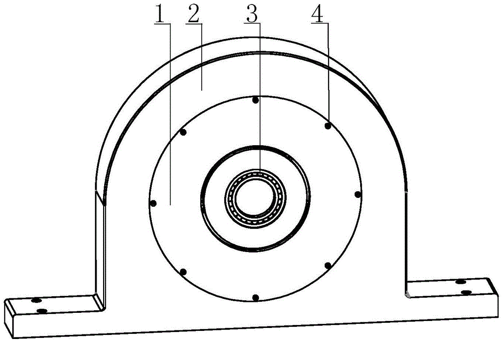
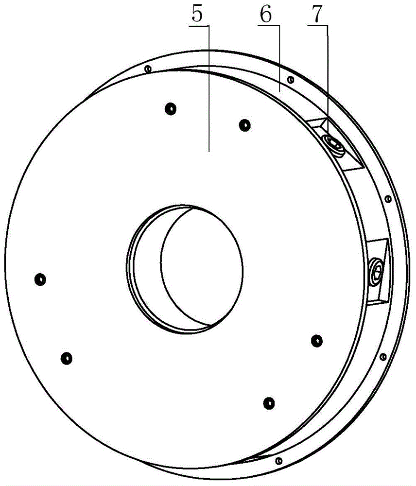
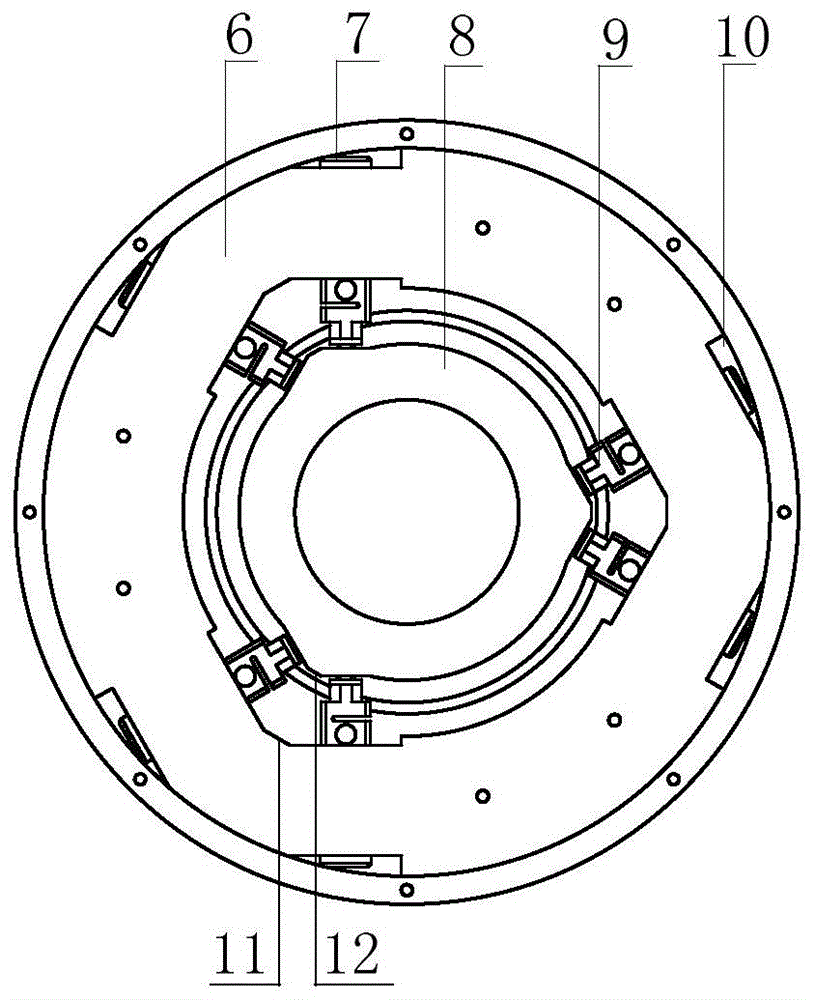
[0018] exist figure 1 In the three-dimensional schematic diagram of the use state of the plane parallel three-dimensional force sensor shown, the sensor 1 of the present invention is fixed on the bearing seat 2 by the fastener 4 through the end plate on the fixing ring, and the bearing 3 to be tested is placed in the force measuring ring . exist figure 2 , image 3 and Figure 4 In the schematic diagram of the plane parallel three-dimensional force sensor shown, three sets of symmetrical triangular notch grooves 10 are evenly distributed on the outer ring surface of the annular fixed ring 6, and the angle between the extended surfaces of the bottom of the two notch grooves is 120°, each The set of triangular notch grooves and the outer ring surface they clamp are approximately in the shape of an isosceles trapezoid, and the bottom of each set of triangular notch grooves, that is, the two waists of the trapezoid, is provided with a stepped through hole whose center line is ...


PUM


Abstract

A plane parallel connection three-dimensional force sensor mainly comprises a fixed ring, a force measuring ring, six force measuring branches and a cover plate, wherein three groups of symmetric triangular notch grooves are uniformly distributed in the outer annular surface of the fixed ring; an included angle formed by the bottom extension surfaces of two notch grooves is 120 degrees; stepped through holes are formed in the bottoms of each group of triangular notch grooves, the center lines of the stepped through holes are perpendicular to the bottoms of the triangular notch grooves, an opening in the other end of each stepped through hole is formed in the triangular notch groove in the inner annular surface of the fixed ring, three groups of isosceles-trapezoid-like notch grooves corresponding to the outer annular surface are formed in the inner annular surface, the annular force measuring ring is arranged in the inner annular surface of the fixed ring, three trapezoid bosses corresponding to the three groups of triangular notch grooves in the inner annular surface of the fixed ring are arranged on the outer annular surface, and a cylindrical slotted hole is formed in each of two lateral surfaces of each trapezoid boss; the force measuring branches are arranged in the stepped through holes of the fixed ring and the corresponding cylindrical slotted holes of the force measuring ring, and two force measuring branches of each group are symmetrically arranged; the cover plate is arranged on the end face of the fixed ring. The plane parallel connection three-dimensional force sensor is simple in structure, convenient to assemble and debug, small in multi-dimensional coupling and high in measuring accuracy, and can synchronously measure the radial force and friction torque of a bearing on line.

Description

technical field [0001] The invention relates to a multidimensional force sensor. Background technique [0002] Bearings are important parts in rotating machines and are most widely used in various mechanical departments. Because it has a series of significant advantages, such as: small friction coefficient, high motion precision, insensitive to the viscosity of lubricant, and can bear load at low speed. Some bearings can also withstand both radial and axial forces, however, bearings are also one of the most vulnerable parts of a machine. According to statistics, 30% of the failures of rotating machinery are caused by bearings. Therefore, the fault monitoring and diagnosis of bearings has been the focus of the development of mechanical fault diagnosis technology at home and abroad in recent years. The current bearing detection technology is mostly based on extracting its vibration signals. For some large key bearings, how to detect their abnormalities as early as possible,...

Claims


Application Information

Patent Timeline
Patent Type & Authority Patents(China)
IPC IPC(8): G01L5/00G01M13/04
Inventor 赵延治杨真真张彩凤焦雷浩
Owner YANSHAN UNIV
Learn More