Automatic focusing device for imaging flow cytometer

A flow cytometer and auto-focus technology, applied in the field of optical instruments, can solve problems such as low energy utilization, high equipment cost, and complex structure, and achieve high energy utilization, compact size, and good signal-to-noise ratio Effect

Inactive Publication Date: 2015-04-29
CHANGCHUN INST OF OPTICS FINE MECHANICS & PHYSICS CHINESE ACAD OF SCI
View PDF5 Cites 7 Cited by
  • Summary
  • Abstract
  • Description
  • Claims
  • Application Information

AI Technical Summary

Problems solved by technology

[0004] However, its autofocus device uses two confocal optical systems to detect the defocusing direction and defocusing amount of the cells, and the structure is complex; its laser light source uses side scattering, and the energy utilization rate is not high, requiring high-power lasers, equipment higher cost

Method used


Image

  • Automatic focusing device for imaging flow cytometer
  • Automatic focusing device for imaging flow cytometer

Examples


Embodiment Construction

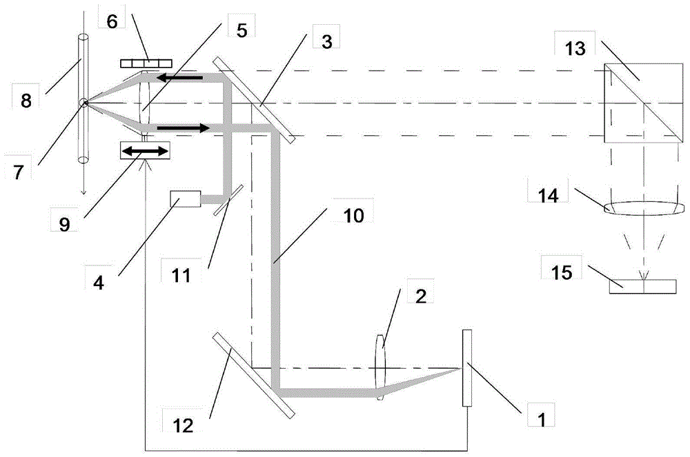
[0010] The following is a detailed description of an imaging flow cytometer autofocus device proposed in this patent with reference to the accompanying drawings. figure 1 is an embodiment of the present invention in an imaging flow cytometry device.

[0011] The imaging flow cytometer device embodied in the present invention is composed of the following parts: a liquid flow system, an auto-focus system and an imaging system. The liquid flow system includes a liquid flow chamber 8 and a cell to be tested 7; the autofocus system includes a focus detector 1, a focus lens 2, a dichroic mirror 3, a laser 4, a microscope objective lens 5, a position sensor 6, a micro displacement mechanism 9, The first reflective plate 11 and the second reflective plate 12 ; the imaging system includes a dichroic mirror stack 13 , an imaging objective lens 14 and an imaging photoelectric sensor device 15 .

[0012] The laser 4 is used as the light source of the auto-focus system, a high-power semic...


PUM

PropertyMeasurementUnit
thicknessaaaaaaaaaa
reflectanceaaaaaaaaaa

Abstract

The invention provides an automatic focusing device for an imaging flow cytometer, and belongs to the field of optical instruments in biology and medicine. The device comprises a focusing detector, a focusing lens, a light splitting plate, a laser, a microscope objective, a position sensor and a micro displacement mechanism, wherein the laser is used for emitting collimation laser with field angles, the collimation laser is reflected by the light splitting plate to be focused through the microscope objective on cells to be measured in a liquid flow chamber, the back scattered light of the cells to be measured passes through the microscope objective to penetrate through the light splitting plate and is converged into the position sensor through the focusing lens, the position sensor is used for calculating the defocusing amount, and the defocusing amount is fed back to the position sensor and the micro displacement mechanism which are arranged on the microscope objective; the focusing function is realized through the movement of the micro displacement mechanism and the measurement of the position sensor. The device adopts a laser spot imaging method, and the defocusing amount of the cells can be directly and accurately obtained; the defocusing amount of the cells is tested through the back scattering of the cells, the usage ratio of the energy is higher, and the signal to noise ratio of the whole system is better; the volume of the system is more compact and simpler.

Description

technical field [0001] The invention belongs to the field of biological and medical optical instruments, and relates to a novel autofocus device of an imaging flow cytometer. Background technique [0002] Flow cytometry is a technique for rapid quantitative analysis and sorting of cells or other biological particles (such as microspheres, bacteria, small model organisms, etc.) arranged in a single row in a liquid flow. Imaging flow cytometry can not only obtain population analysis data of a large number of cells, but also can see cell images in real time, and the analysis results of each step can be confirmed by images. [0003] At present, imaging flow cytometry has gained great attention in the world. Amnis, a subsidiary of Merck Millipore in the United States, has produced imaging flow cytometers with good performance. The models include Image Stream Mark II and Flow Sight. etc., can capture up to 12 high-resolution images of each flow cell in real time, the detection ra...

Claims


Application Information

Patent Timeline
Patent Type & Authority Applications(China)
IPC IPC(8): G01N15/14
Inventor 李灿刘英孙强赵建
Owner CHANGCHUN INST OF OPTICS FINE MECHANICS & PHYSICS CHINESE ACAD OF SCI
Why Eureka
Try Eureka