Detection method for defects of compound insulator, equipment and system

A technology for composite insulators and defects, applied in the field of electric power, can solve problems that affect the accuracy of detection results, no detection, abnormal temperature rise of composite insulators, etc., and achieve the advantages of improving convenience and application range, improving accuracy, and strong penetrating ability Effect

Inactive Publication Date: 2015-04-29
TIANSHENGQIAO BUREAU CSG EHV POWER TRANSMISSION CO +1
View PDF1 Cites 12 Cited by
  • Summary
  • Abstract
  • Description
  • Claims
  • Application Information

AI Technical Summary

Problems solved by technology

[0004] The disadvantages of the above infrared detection method are: due to the temperature, humidity and sunshine of the external environment, factors such as pollution flashover, rain flashover, guano flashover and leakage current on the surface of the composite insulator wil

Method used


Image

  • Detection method for defects of compound insulator, equipment and system
  • Detection method for defects of compound insulator, equipment and system
  • Detection method for defects of compound insulator, equipment and system

Examples


Embodiment 1

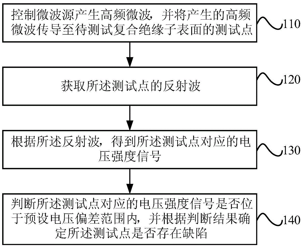
[0032] see Figure 1a , is a flow chart of a method for detecting defects of a composite insulator provided in Embodiment 1 of the present invention.

[0033] The method includes: step 110 - step 140 .

[0034] Step 110, controlling the microwave source to generate high-frequency microwaves, and transmitting the generated high-frequency microwaves to test points on the surface of the composite insulator to be tested.

[0035] In this step, the frequency of the high-frequency microwaves generated by the microwave source may be above 10 GHz. The detection accuracy of composite insulator defects is positively correlated with the frequency of high-frequency microwaves emitted by microwave sources, that is, the higher the frequency of high-frequency microwaves emitted by microwave sources, the higher the detection accuracy of composite insulator defects; The lower the frequency of the microwave, the lower the detection accuracy of the defects of the composite insulator.

[0036] ...

example 1

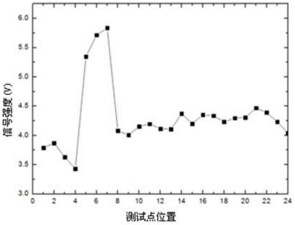
[0056] In this example, a series of pore defects with a diameter of 1 mm were artificially manufactured in the composite insulator to be tested, and 24 test points were detected along a circumferential surface of the composite insulator to be tested. The microwave source was controlled to generate high-frequency microwaves with a frequency of 24 GHz, and Conduct the generated high-frequency microwaves to 24 test points on the surface of the composite insulator to be tested; obtain the reflected waves of each test point, and obtain the corresponding voltage intensity signal of each test point, such as Figure 1c As shown, where the abscissa is the position of the test point, and the ordinate is the voltage intensity signal of the reflected wave corresponding to each test point, it can be seen that the voltage intensity signal of the reflected wave at the non-defect position is distributed within the range of 4.0V±0.6V, The average value of the voltage intensity signal of the ref...

example 2

[0059] In this example, the composite insulator to be tested is a composite insulator taken from the N46 tower of Lingshen Line B, and 24 test points are detected along a circumferential surface of the composite insulator to be tested, and the microwave source is controlled to generate high-frequency microwaves with a frequency of 24GHz. And conduct the generated high-frequency microwaves to 24 test points on the surface of the composite insulator to be tested; obtain the reflected waves of each test point, and obtain the corresponding voltage intensity signal of each test point, such as Figure 1d As shown, where the abscissa is the position of the test point, and the ordinate is the voltage intensity signal of the reflected wave corresponding to each test point, it can be seen that the voltage intensity signal of the reflected wave at most positions is distributed within the range of 6.9V±0.5V, Therefore, the average value of the voltage intensity signal of the reflected wave...


PUM

PropertyMeasurementUnit
Frequencyaaaaaaaaaa

Abstract

The embodiment of the invention provides a detection method for the defects of a compound insulator, equipment and a system. The detection method comprises the following steps of: controlling a microwave source to generate high-frequency microwave, conducting the generated high-frequency microwave to a tested point on the surface of the compound insulator to be tested; acquiring reflected wave of the tested point; according to the reflected wave, and obtaining a voltage intensity signal corresponding to the tested point; judging whether the voltage intensity signal corresponding to the tested point is in the preset voltage-deviation range, and judging whether the defects exist on the tested point according to the judgment result. The detection method, the equipment and the system provided by the embodiment of the invention have the advantages that since the compound insulator adopts a non-metal material, the penetrability of the high-frequency microwave in the non-metal material is strong, surface contact and a coupling agent are not needed and non-destructive detection for the defects in the compound insulator can be realized on the basis of the reflected wave, so that the convenience and the application range of detection are improved; and since the measurement result is not dependent on the temperature, the humidity and the sunshine condition of the ambient environment, the accuracy of the detection result is improved.

Description

technical field [0001] Embodiments of the present invention relate to the field of electric power technology, and in particular, to a method, device and system for detecting defects of composite insulators. Background technique [0002] Composite insulators are more and more widely used in power systems due to their small size, light weight, excellent hydrophobicity and hydrophobic mobility, good internal insulation performance, high mechanical strength, and small corona and electromagnetic interference. There are still a small number of composite insulators that have defects and cause accidents, so it is necessary to detect the defects of composite insulators. Therefore, the detection technology of composite insulator defects has emerged as the times require. [0003] Leakage current will be generated at the defects of composite insulators, and abnormal temperature rise will occur under the action of alternating electric field. The existing infrared detection method genera...

Claims


Application Information

Patent Timeline
IPC IPC(8): G01N22/02
Inventor 赵伟王黎明李昂陈荣盛冉学彬赵庆州
Owner TIANSHENGQIAO BUREAU CSG EHV POWER TRANSMISSION CO
Why Eureka
Try Eureka