A large mask reshaping device and method

A technology of shaping device and large mask, which is applied in photoplate making process exposure device, photoplate making process of pattern surface, microlithography exposure equipment, etc., to achieve the effect of convenient operation, simple structure and solving the problem of imaging quality

Active Publication Date: 2019-04-30
SHANGHAI MICRO ELECTRONICS EQUIP (GRP) CO LTD
View PDF6 Cites 0 Cited by
  • Summary
  • Abstract
  • Description
  • Claims
  • Application Information

AI Technical Summary

Problems solved by technology

[0008] The purpose of the present invention is to provide a large reticle shaping device and method to solve the problem of imaging quality caused by the deformation of the large reticle in the existing photolithography device

Method used


Image

  • A large mask reshaping device and method
  • A large mask reshaping device and method
  • A large mask reshaping device and method

Examples


Embodiment 1

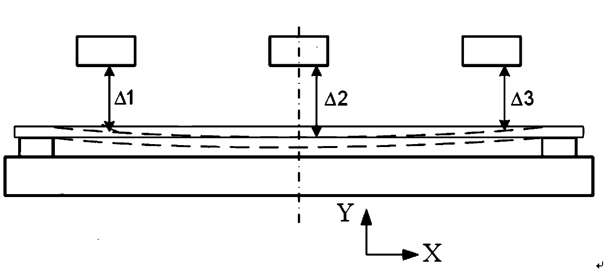
[0069] like Figure 4 and 5 As shown, the present invention provides a large reticle shaping device, the X direction is the scanning direction, and the Y direction is the non-scanning direction. Several groups of measuring devices 301; wherein,

[0070] The large reticle 304 is fixed on the stage 303 by vacuum adsorption;

[0071] The vertical lifting mechanism 302 and the measuring device 301 are arranged vertically opposite to the large reticle 304 respectively, and have a certain gap with the upper surface of the large reticle 304, and are horizontally arranged near the field of view of the objective lens;

[0072] Specifically, the vertical lifting mechanism 302 and the measuring device 301 are respectively arranged on the first side (upper side in the figure) of the large reticle 304, and each set of vertical lifting mechanisms 302 corresponds to a set of measuring devices 301, the measuring device 301 is arranged adjacent to the corresponding vertical lifting mechanis...

Embodiment 2

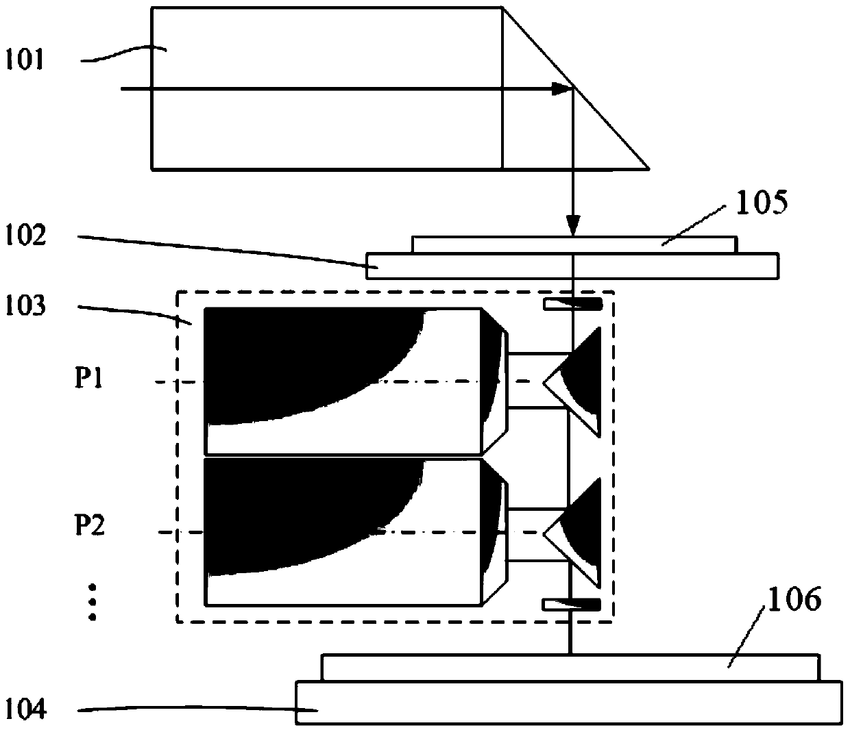
[0104] In Embodiment 1, the measuring device is arranged in conjunction with the vertical lifting mechanism (that is, a set of vertical lifting mechanisms is equipped with a set of measuring devices), and is arranged above the large reticle (Mask). The measuring device is arranged near the vertical lifting mechanism to complete the measurement of the vertical position of the large reticle (Mask), and feed back the measured position signal to the vertical lifting mechanism, so that the vertical lifting mechanism can adjust the vertical position of the large mask in real time. The amount of deformation effectively guarantees the shaping effect of the shaping device. Realize the closed-loop control of the vertical deformation of the large reticle.

[0105] like Figure 11 and 12As shown, since the deformation of the large reticle 704 (Mask) in the vertical direction is basically the same as the deformation along the X direction, only one set of measuring devices 701 can be arra...

Embodiment 3

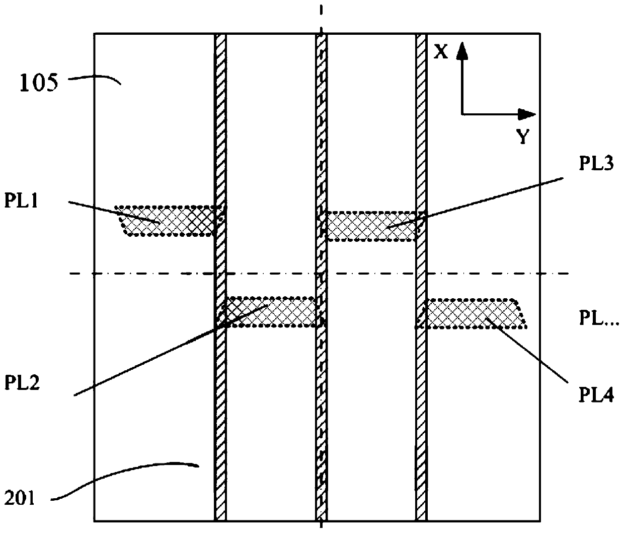
[0110] Embodiment 3 differs from the mask of Embodiment 2 in that, as Figure 13 and 14 As shown, three sets of measuring devices arranged at intervals in the Y direction are arranged under the large reticle, that is to say, the vertical lifting mechanism 901 is arranged vertically opposite to the first side of the large reticle 904;

[0111] Three sets of measuring devices 903 are arranged vertically opposite to each other on the second side of the large reticle 904 (lower in the figure), and are connected to a measuring device base 904;

[0112] The vertical lifting mechanism 901 and the same group of measuring devices 903 in the same position in the non-scanning direction are matched with each other.

[0113] In this embodiment, one set of measuring devices 903 and three sets of vertical lifting mechanisms 901 are arranged at intervals in the X direction, and three sets of measuring devices 903 and three sets of vertical lifting mechanisms 901 are arranged at intervals in ...


PUM

PropertyMeasurementUnit
thicknessaaaaaaaaaa

Abstract

The invention provides a device and method for shaping a large mask plate. The device comprises a large mask plate, a plate bearing bench, multiple vertical lifting mechanisms and multiple measurement devices. The large mask plate is fixed to the plate bearing bench. The measurement devices are used for feeding the measured large mask plate position signal back to the corresponding vertical lifting device. The vertical lifting device adjusts a vertical position of the large mask plate according to the feedback signal. The device utilizes the vertical lifting mechanisms and the multiple measurement devices to shape the large mask plate so that real-time close-cycle control of large mask plate vertical deflection is realized, large mask plate shaping effects are effectively guaranteed and the problem of poor imaging quality caused by large mask plate self-weight deformation is solved. The device has a simple structure and is convenient for operation.

Description

technical field [0001] The invention relates to the technical field of integrated circuits, in particular to a large mask shaping device and method. Background technique [0002] The lithography apparatus in the prior art is mainly used in the field of integrated circuit IC or flat panel display and the manufacture of other micro devices. With a lithographic apparatus, multiple layers of masks with different mask patterns are sequentially imaged with precise alignment on a photoresist-coated wafer, such as a semiconductor wafer or an LCD panel. [0003] Lithography devices are generally divided into two categories, one is a stepper lithography device, the mask pattern is imaged on one exposure area of ​​the wafer at one time, and then the wafer moves relative to the mask to move the next exposure area to the mask pattern. and below the projection objective, the mask pattern is again exposed on another exposed area of ​​the wafer, and the process is repeated until all expose...

Claims


Application Information

Patent Timeline
Patent Type & Authority Patents(China)
IPC IPC(8): G03F1/68G03F7/20
CPCG03F1/68G03F7/70716
Inventor 江旭初王鑫鑫魏龙飞梁晓叶
Owner SHANGHAI MICRO ELECTRONICS EQUIP (GRP) CO LTD
Why Eureka
Try Eureka