Weldment hydraulic shaping device

A technology for shaping devices and welding parts, which is applied in the direction of feeding devices, positioning devices, storage devices, etc., can solve the problems of affecting the shaping quality of welding parts, poor shaping effect of welding parts, and poor applicability of correcting machinery, so as to prevent secondary deformation , good shaping quality and strong applicability

Inactive Publication Date: 2021-02-09
苏州市华振机械电器有限公司
View PDF7 Cites 0 Cited by
  • Summary
  • Abstract
  • Description
  • Claims
  • Application Information

AI Technical Summary

Problems solved by technology

[0007] For this reason, the embodiment of the present invention provides a welding piece hydraulic shaping device, through the setting of the correction component, it can clamp and shape the welding pieces of different sizes, which has strong applicability and convenient operation, so that the shaping quality of the welding piece is good, and the shaping High efficiency, through the setting of the limit component, the straightening machine can clamp the qualified part of the weldment while shaping the deformed part of the weldment, and protect the qualified part of the weldment to prevent secondary deformation. The shaping effect of the weldment is guaranteed to solve the problem that in the prior art, it is difficult to clamp the qualified part of the weldment during the shaping process of the existing straightening machine, which causes unnecessary deformation of the qualified part of the weldment and further increases the scrap The rate makes the shaping effect of the weldment poor, the applicability of the existing correction machine is poor, it is difficult to correct the weldment of different sizes and shapes, it is inconvenient to operate, and the problem of affecting the shaping quality of the weldment

Method used


Image

  • Weldment hydraulic shaping device
  • Weldment hydraulic shaping device
  • Weldment hydraulic shaping device

Examples


Embodiment Construction

[0033] The implementation mode of the present invention is illustrated by specific specific examples below, and those who are familiar with this technology can easily understand other advantages and effects of the present invention from the contents disclosed in this description. Obviously, the described embodiments are a part of the present invention. , but not all examples. Based on the embodiments of the present invention, all other embodiments obtained by persons of ordinary skill in the art without making creative efforts belong to the protection scope of the present invention.

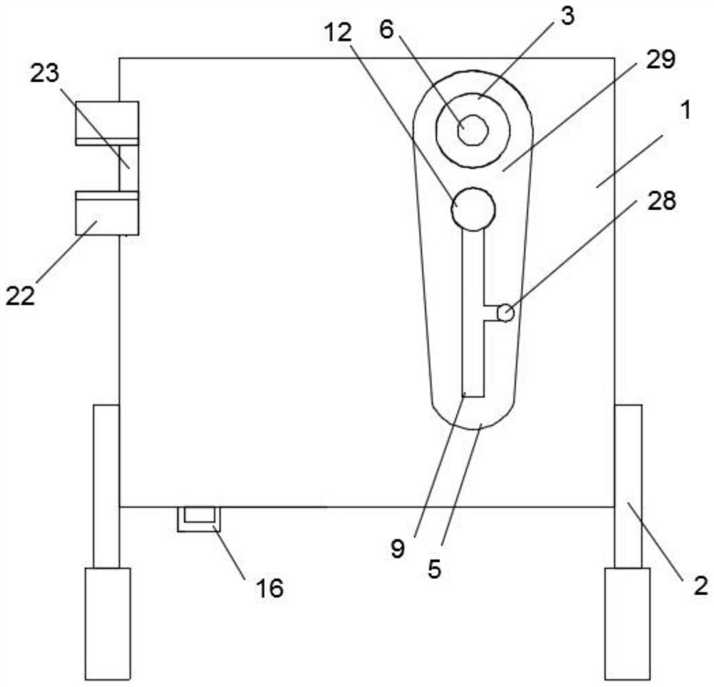
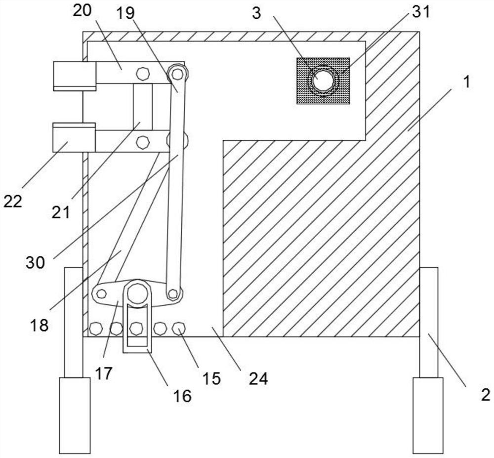
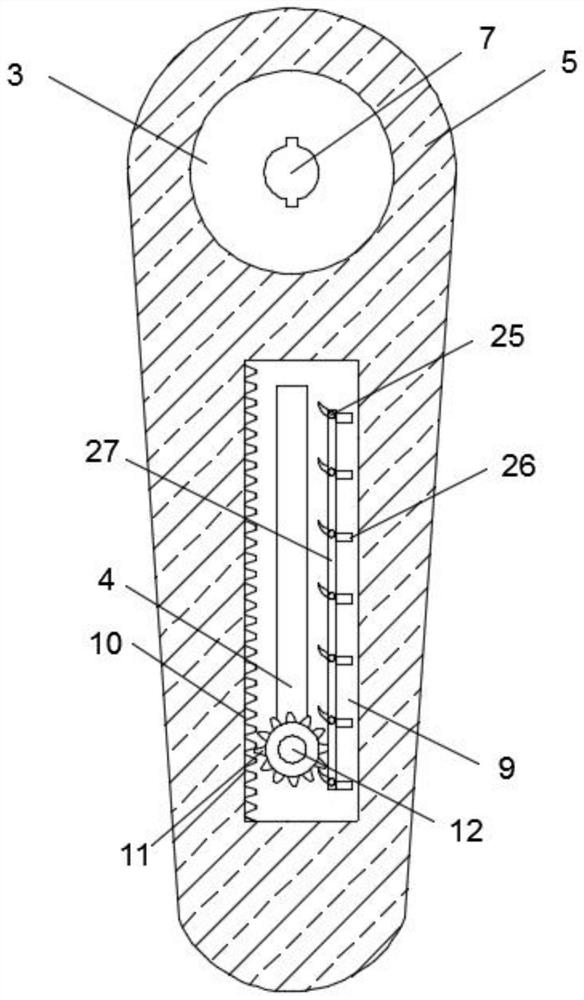
[0034] Refer to the attached figure 1 , image 3 with Figure 5-8 , a weldment hydraulic shaping device in this embodiment, comprising an operating panel 1, a first hydraulic rotating motor 31, a second hydraulic rotating motor 32 and an armrest 2, and the operating panel 1 is fixedly fixed with the armrests 2 on both sides, so The operation panel 1 is provided with a transmission groove 24, a...


PUM


Abstract

The invention discloses a weldment hydraulic shaping device, and particularly relates to the technical field of weldment shaping machining. The weldment hydraulic shaping device comprises an operationpanel, a first hydraulic rotating motor, a second hydraulic rotating motor and armrests, wherein the armrests are symmetrically and fixedly installed on the two sides of the operation panel. According to the weldment hydraulic shaping device provided by the invention, through the arrangement of a correcting assembly, the first hydraulic rotating motor is started to drive a matching cam to rotatein a reciprocating mode, a pushing shaft is made to bend a horizontal weldment around a matching cylinder, and weldments with different sizes can be clamped and shaped, so that applicability is high,operation is conducted conveniently, and the shaping quality of the weldment is good; and through the arrangement of a limiting assembly, when a transmission long plate moves forwards, a transmissionshort plate moves backwards, clamping blocks at the end parts of connecting plates clamp inwards, otherwise, the clamping blocks loosen outwards, so that a correction machine clamps and protects the qualified part of the weldment while shaping the deformed part of the weldment, secondary deformation of the qualified part of the weldment is prevented, and the shaping effect of the weldment is ensured.

Description

technical field [0001] The embodiment of the present invention relates to the technical field of welding piece shaping processing, and in particular to a welding piece hydraulic shaping device. Background technique [0002] Welding: also known as welding and welding, is a manufacturing process and technology for joining metal or other thermoplastic materials such as plastics by means of heating, high temperature or high pressure. Welding achieves the purpose of joining through the following three ways: [0003] 1. Fusion welding: Heating the workpieces to be joined to make them partially melt to form a molten pool. After the molten pool is cooled and solidified, it can be joined. If necessary, fillers can be added to assist. It is suitable for welding of various metals and alloys without pressure. . [0004] 2. Pressure welding: pressure is applied to the weldment during the welding process, which belongs to the processing of various metal materials and some metal material...

Claims


Application Information

Patent Timeline
Patent Type & Authority Applications(China)
IPC IPC(8): B21D3/00B21D43/00
CPCB21D3/00B21D43/003
Inventor 顾国正
Owner 苏州市华振机械电器有限公司
Why Eureka
Try Eureka