A wide beam scanning exposure method

A technology of scanning exposure and wide beam, applied in the field of scanning exposure, can solve problems such as roughness error, achieve the effect of overcoming seam problem and eliminating phase error

Active Publication Date: 2016-09-21
TSINGHUA UNIV
View PDF3 Cites 2 Cited by
  • Summary
  • Abstract
  • Description
  • Claims
  • Application Information

AI Technical Summary

Problems solved by technology

Although the above three grating manufacturing methods may reduce the stray light introduced by the grating pitch error by adjusting the optical path, the existence of laser speckle makes the high-frequency groove shape and roughness errors inevitable

Method used


Image

  • A wide beam scanning exposure method
  • A wide beam scanning exposure method

Examples


Embodiment Construction

[0013] The present invention will be described in detail below in conjunction with the accompanying drawings and embodiments.

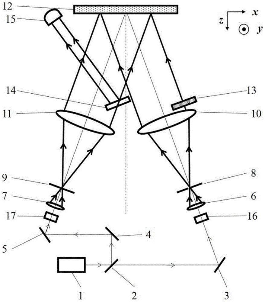
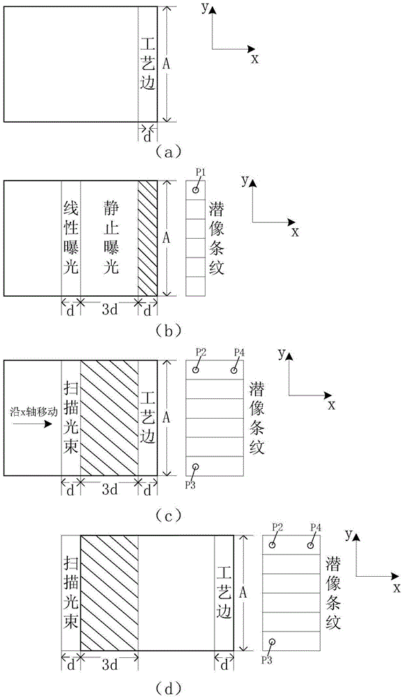
[0014] The working principle of the wide-beam scanning exposure method of the present invention is: on the basis of locking the phase and attitude of the exposure beam relative to the substrate, use a collimator lens aperture of 1 / 10 to 1 / 5 wide beam to scan and expose along the grating vector. The beam width can be adjusted according to actual needs. The narrow beam quality is good, but the exposure time is long; the wide beam quality is relatively poor, but the exposure time is short. During the exposure process, the interference field and the substrate are required to move strictly at the same speed and direction (the entire interference field does not move, but the phase of the interference field is shifting), otherwise the interference fringes recorded in the photoresist coated on the surface of the substrate will be smoothed out. When the subst...


PUM


Abstract

The invention relates to a wide light beam scanning exposure method which comprises the following steps: setting a double-beam exposure system, taking the direction along the grating vector in the double-beam exposure system as the x direction, taking the direction along the grating line as the y direction, and taking the direction along the substrate normal as the z direction; exposing a process edge with the area of A*d on the right edge of the substrate by utilizing an interference field formed on the surface of the substrate, pushing the process edge into a first attenuation wedge and a second attenuation wedge, and forming latent image stripes with the area of A*d on the process edge; performing t-time static exposure on an area with the area of A*3d on the left side of the process edge, and performing linear exposure on an area with the area of A*d positioned on the left side of the area with the area of A*3d; forming latent image stripes with the area of A*3d by virtue of the first and second latent image stripes; and sequentially performing scanning exposure on total areas on the left side of the latent image stripes with the area of A*3d by utilizing light beams with the width of d until the left edge of the substrate leaves the right edge of the exposure beams, and ending the scanning exposure process.

Description

technical field [0001] The invention relates to a scanning exposure method, in particular to a wide beam scanning exposure method. Background technique [0002] Diffraction gratings, as a typical diffractive optical element, are widely used in the fields of spectral analysis, precision metrology, integrated optics, information processing, and laser pulse compression. At present, the manufacturing methods of large-scale holographic gratings mainly include single exposure, scanning exposure and exposure splicing. Streak locking during exposure is critical. The two-beam holographic exposure method is the most common method for fabricating holographic gratings. [0003] The Lawrence Livermore National Laboratory of the United States uses an exposure lens with a diameter of 1.09m to produce an area of ​​910×450mm in a single exposure. 2 raster. The advantage of single exposure lies in the mature technology and simple system. The disadvantage is that the area and quality of th...

Claims


Application Information

Patent Timeline
Patent Type & Authority Patents(China)
IPC IPC(8): G03F7/20
Inventor 马冬晗曾理江
Owner TSINGHUA UNIV
Why Eureka
Try Eureka