
Patsnap Eureka
For R&D, Patsnap Eureka makes reading and utilizing patents & technical documents easy.
Patsnap Eureka AIR
Designed for self-driven R&D workflows. Generate viable solutions, solve complex R&D challenges, empower your innovation with AI.

Patsnap Eureka Materials
Designed for material experts only. Revolutionize your material R&D, from search, analyze, to developing new materials.

TechResearch
Generate reliable direction feasibility study reports for your R&D in just a few steps.

TechSeek
Discover and master advanced knowledge NOW. Basics, ideas, possibilities, all at once.

TechMind
As an expert in R&D Theories, TechMind can generates customized viable solutions instantly.

TechRisk
Analyze your overall solution with one click, know your potential R&D risks in advance.

TechMonitor
Get weekly tech updates, stay abreast of the latest tech innovations and key insights.
System for picosecond pulse test of device units of phase change memory
A phase-change memory and pulse test technology, applied in static memory, instruments, etc., can solve problems such as no test system
- Summary
- Abstract
- Description
- Claims
- Application Information
AI Technical Summary
Problems solved by technology
Method used
Image

Examples
Embodiment 1
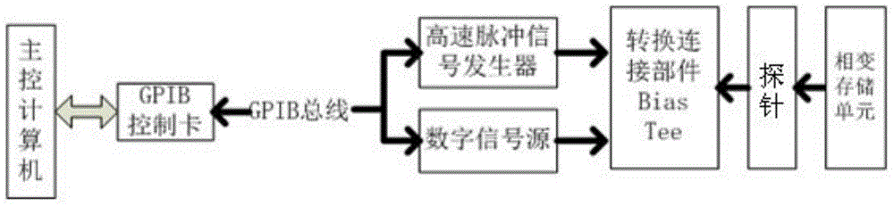
[0038] The test system is composed of a main control computer, a picosecond pulse signal generator, a digital source meter, a high-speed oscilloscope and a device fixture box. The main control computer is connected to the picosecond level high-speed pulse signal generator and the digital source meter through the GPIB interface bus. Connect the pulse signal generator and digital source meter to the biaser in the fixture box through the control cable. The main control computer transmits commands and collects data between the pulse signal generator and the digital source meter through the GPIB card. The two probes of the device fixture box are respectively connected to the upper electrode and the lower electrode of the phase change memory, forming a complete memory unit test connection circuit. Adjust and control the four test modules of current and voltage, voltage and current, resistance and write pulse height, resistance and wipe pulse height in the operating software, and coo...
Embodiment 2
[0041] Change the voltage-current test module used in embodiment 1 into a resistance and write pulse height test module, and the specific test parameters are as follows: the pulse current amplitude test range is 0-7.5V, the pulse width is 8000ps, and the rest are the same as in embodiment 1 , record the corresponding pulse height and resistance value to get the resistance-pulse height curve (such as Image 6 shown). Depend on Image 6 It is known that when the pulse amplitude is less than 4V, the resistance is very low, and the phase change film is still in a polycrystalline state, because the phase change material will not melt under smaller energy, so the amorphous state cannot be obtained. As the pulse amplitude increases, the resistance increases rapidly, indicating that the phase change material has been melted and transformed into a high-resistance amorphous state. When the pulse amplitude is greater than 4V, increasing the pulse amplitude has no effect on increasing t...
PUM
 Abstract
Description
Claims
Application Information
 - R&D Engineer
- R&D Manager
- IP Professional
- Industry Leading Data Capabilities
- Powerful AI technology
- Patent DNA Extraction
Browse by: Latest US Patents, China's latest patents, Technical Efficacy Thesaurus, Application Domain, Technology Topic, Popular Technical Reports.
© 2024 PatSnap. All rights reserved.Legal|Privacy policy|Modern Slavery Act Transparency Statement|Sitemap|About US| Contact US: help@patsnap.com