

Voltage and current switchable type electric leakage protection device
A leakage protection device, voltage and current technology, applied in the direction of emergency protection circuit devices, circuit devices, emergency protection devices with automatic disconnection, etc., can solve the problems of staying in the principle stage, poor anti-interference of the detection circuit, high input impedance, etc., to achieve Improve anti-interference, good anti-interference effect
- Summary
- Abstract
- Description
- Claims
- Application Information
AI Technical Summary
Problems solved by technology
Method used
Image

Examples
Embodiment 1
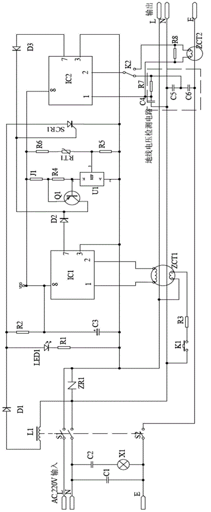
[0018] Such as figure 1 As shown in the schematic diagram of the circuit, the voltage and current switchable leakage protection device of the present invention includes a release L1, a rectifier diode D1, a thyristor SCR1, an indicator light circuit consisting of LED1 and a resistor R1, and a step-down circuit consisting of a resistor R2 Composition, first amplifying circuit IC1, zero-sequence current transformer ZCT1, test circuit consists of switch K1 and resistor R3, second amplifying circuit IC2 and over-temperature detection circuit (composed of voltage reference source U1, resistor R4, resistor R5, resistor R6 , triode Q1 and thermistor RT), the second amplifying circuit IC2 is also provided with a ground current transformer ZCT2 and a ground voltage detection circuit; the ground voltage detection circuit includes a first capacitor C4, a second capacitor C5, the third capacitor C6 and the adjusting resistor R7; one end of the first capacitor C4 is connected to the neutra...
Embodiment 2
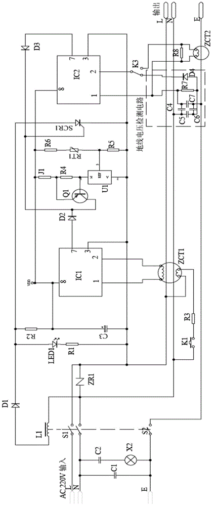
[0033] The principles and beneficial effects of this embodiment and Embodiment 1 are basically the same, the difference lies in: figure 2 As shown, the ground wire voltage detection circuit is also provided with a fourth capacitor C7 and a diode D4, the first to fourth capacitors form a capacitor bridge, and the common end of the first capacitor C4 and the fourth capacitor C7 is connected to an adjustment resistor One end of R7, the common end of the second capacitor C2 and the third capacitor C3 are connected to the other end of the adjusting resistor R7 and the anode of the diode D4, and the cathode of the diode D4 is connected to the transfer switch K2. The live voltage of the local line is extracted by the coupling and rectification of C6 and D4, the signal is sent to the 2 pin of IC2 through the switch K2, and the signal is extracted by C4 and sent to the 1 pin of IC2, the resistor R7 is used to adjust the detection sensitivity of IC2, C5, C7 In order to adjust the balan...
PUM
 Abstract
Description
Claims
Application Information