Multi-dimensional rotation type wireless electric transmission device

A wireless power transmission, rotary technology, applied in circuit devices, electrical components, electromagnetic wave systems, etc., can solve problems such as reduced energy transfer efficiency, inability to meet load power supply conditions, and failure to solve power supply problems.

Active Publication Date: 2015-04-29
SOUTH CHINA UNIV OF TECH
View PDF3 Cites 9 Cited by
  • Summary
  • Abstract
  • Description
  • Claims
  • Application Information

AI Technical Summary

Problems solved by technology

[0003] Most of the traditional wireless power transmission devices use inductive wireless power transmission, which is limited by the distance. At the same time, the transmitting coil and the receiving coil must be in a state of facing each other. The application occasions are limited, such as transformers, wireless mobile phone chargers and other traditional methods. Traditional inductive wireless power transmission devices can only transmit energy within a fixed point and direction within a distance of almost contact. If the distance changes or the load position changes, the efficiency of energy transmission will be greatly reduced, which cannot meet the distance requirements. and the power supply situation of loads with changing locations
[0004] The development of the resonant wireless power transmission method has solv

Method used


Image

  • Multi-dimensional rotation type wireless electric transmission device
  • Multi-dimensional rotation type wireless electric transmission device
  • Multi-dimensional rotation type wireless electric transmission device

Examples


Embodiment Construction

[0029] In order to make the technical problems to be solved in the present invention, technical solutions and advantages clearer, the following will be described in detail in conjunction with the accompanying drawings and specific embodiments. Personnel can realize with reference to prior art.

[0030] Aiming at the existing problems of complex structure, high cost, low transmission efficiency and short distance, the present invention provides a multi-dimensional rotary wireless power transmission device.

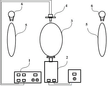
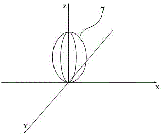
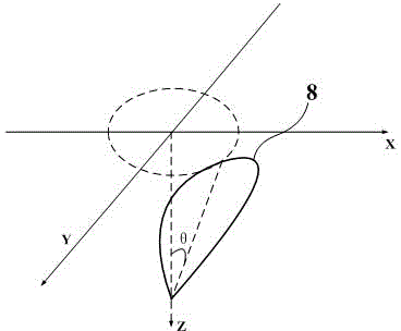
[0031] Such as Figure 1~Figure 3 As shown, this embodiment provides a multi-dimensional rotary wireless power transmission device, including a wireless power transmission device power source 1 , an adjustable rotating motor 2 , a rotating relay coil 3 , a conductive slip ring 4 , a receiving coil 5 and a load 6 . The power source 1 of the wireless power transmission device provides a signal energy source for the rotating relay coil 3, and the rotating relay coil is connec...


PUM


Abstract

The invention provides a multi-dimensional rotation type wireless electric transmission device. The multi-dimensional rotation type wireless electric transmission device comprises an adjustable-speed rotary electric motor, a wireless electric transmitting rotation repeating coil, a receiving coil and a wireless electric transmitting device power source. The wireless electric transmitting rotation repeating coil supplies power to multiple loads of different positions simultaneously through the rotation mode. The non-contact type energy transmission is carried out by the wireless electric transmitting rotation repeating coil and the receiving coil through a resonant mode. According to the multi-dimensional rotation type wireless electric transmission device, a gap exists between the wireless electric transmitting repeating coil and the receiving coil, and the energy transmission is carried out through the resonance mode. The 360 degree omni-directional rotation is carried out on the rotation repeating coil through the adjustable-speed rotary electric motor. The repeating coil is connected with wireless electric transmitting device power source through an electric conduction link. The rotation repeating coil supplies the power to the multiple loads of the different positions simultaneously through the rotation mode. Due to the fact that the rotation mode is utilized by the rotation repeating coil, the position of the rotation repeating coil can be changed. Based on the resonance principle, the simplest simultaneous power supplying to the multiple loads is achieved, and therefore the practicality is good, the cost is low and the efficiency is high.

Description

technical field [0001] The invention relates to a non-contact power transmission technology, in particular to a multi-dimensional rotary wireless power transmission device. Background technique [0002] Since the wireless power transmission technology uses wireless magnetoelectric resonance for charging, the equipment can be invisible, the wear rate of the equipment is low, the application range is wide, and the area of ​​the public charging area is relatively reduced. Moreover, it has high technical content, convenient operation, and can implement relatively long-distance wireless energy conversion, and has been widely used in daily life. [0003] Most of the traditional wireless power transmission devices use inductive wireless power transmission, which is limited by the distance. At the same time, the transmitting coil and the receiving coil must be in a state of facing each other. The application occasions are limited, such as transformers, wireless mobile phone charge...

Claims


Application Information

Patent Timeline
IPC IPC(8): H02J17/00H02J50/12
Inventor 张波关就丘东元
Owner SOUTH CHINA UNIV OF TECH
Why Eureka
Try Eureka